Tech Support: www.steppir.com/support Tel: 425.891.6134 support@steppir.com
Page 35
CHAPTER THREE
SECTION 3.4
MOUNTING THE EHU’S ON THE BOOM (continued)
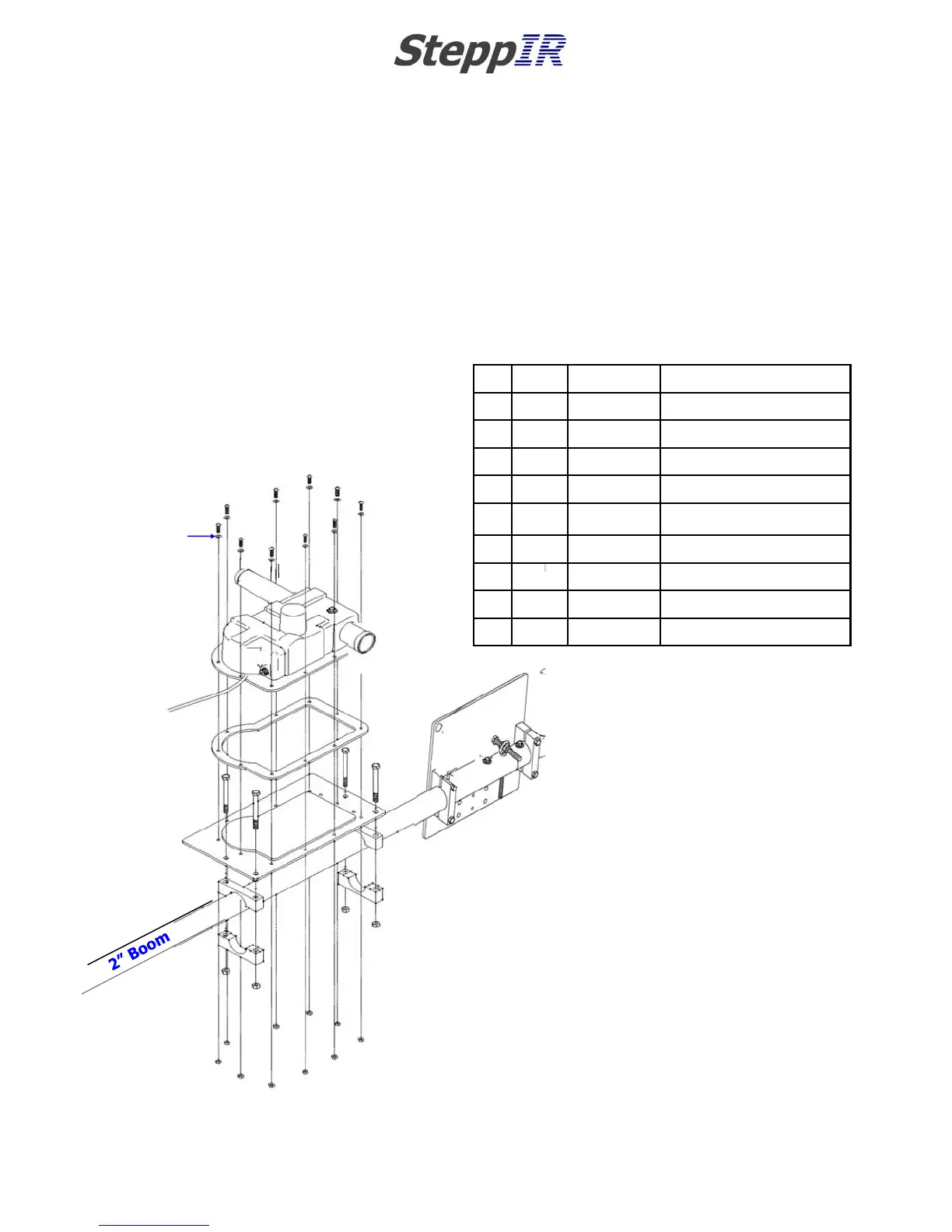
DRIVEN ELEMENT EHU ASSEMBLY DRAWING
The parts explosion drawing in figure 3.40 gives you an overview of the assembly of the driven EHU.
Detailed instructions follow. The DB18 driven element is not a loop, so there is no return tube to install.
Key QTY Part # Description
A 10 60-0017 #10x 3/4” Machine screw
B 10 60-0018 #10 Flat washer
C 10 60-0019 #10 Nylock nut
D 4 60-0065 5/16”x3-1/2” Hex head bolt
E 4 60-0046 5/16” Nylock nut
F 1 70-3403-01 Driven Element EHU
G 1 10-1502-01 Element housing gasket
H 1 10-1015-11 Element mounting plate
J 4 10-1601-22 2” Aluminum saddle half
A (x10)
B (x10)
C (x10)
G
H
J
J
J
J
E
E
E
E
F
D
D
D
D
FIG. 3.40