Tech Support: www.steppir.com/support Tel: 425.891.6134 support@steppir.com
Page 50
Note: If you are wiring the control cable yourself using a 25 pin connector and backshell instead of using the
above dSub field splice, use the same pin numbers shown above. For the 25 pin connector installation, you would
solder the ground wire to the case of the 25 pin connector and then put the backshell on.
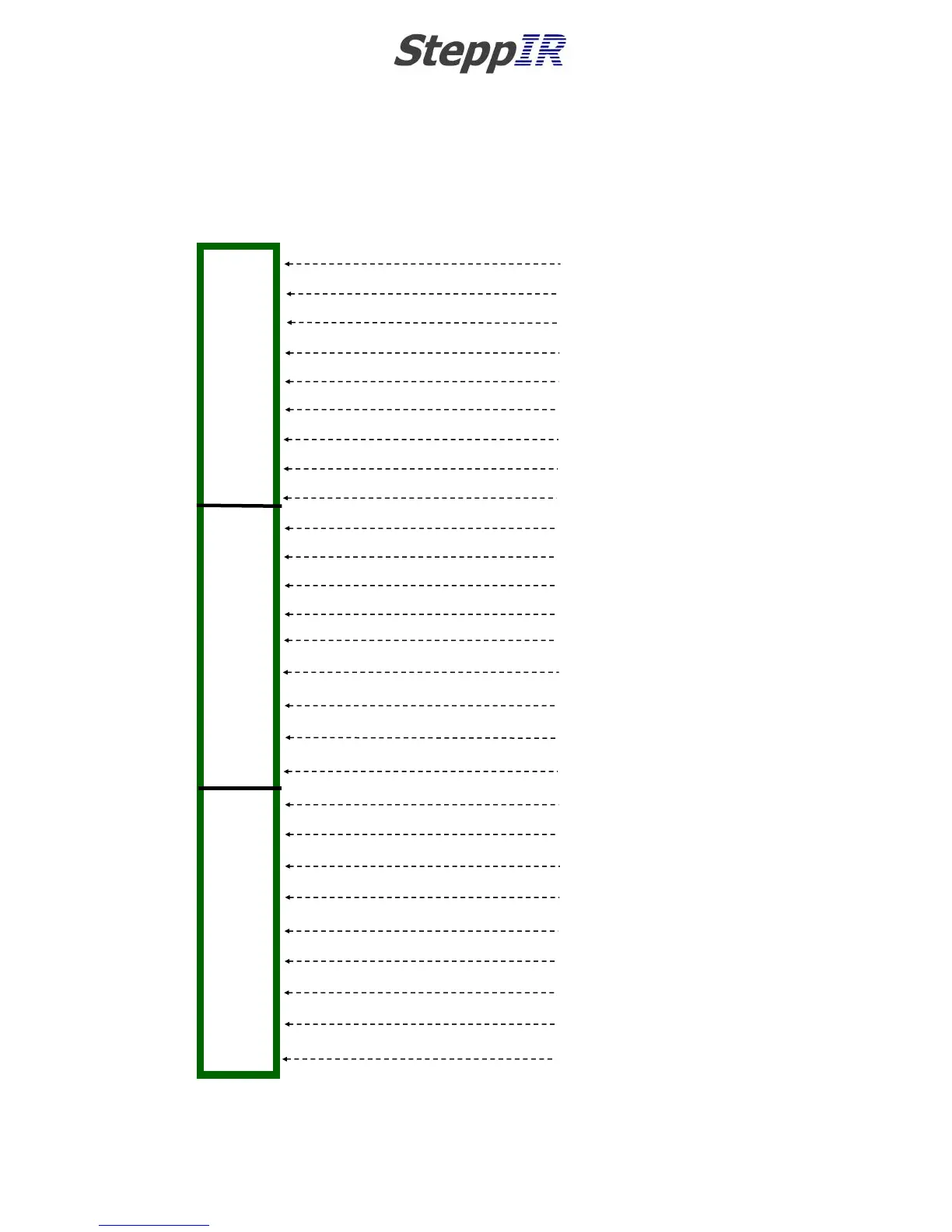
16 WIRE CONTROL CABLE
BLACK
RED
GREEN
WHITE
BROWN
BLUE
ORANGE
YELLOW
VIOLET
GREY
PINK
CRÈME
WHITE/ORANGE STRIPE
NOT USED
NOT USED
NOT USED
NOT USED
NOT USED
NOT USED
NOT USED
NOT USED
WHITE/RED STRIPE
WHITE/BLACK STRIPE
WHITE/GREEN STRIPE
NOT USED
SHIELD WIRE
SHIELD WIRE (CAN GO HERE TOO)
1
2
3
4
5
6
7
8
9
10
11
12
13
14
15
16
17
18
19
20
21
22
23
24
25
G
G
FRONT ROW TERMINAL STRIP
MIDDLE ROW TERMINAL STRIP
BACK ROW TERMINAL STRIP
25 PIN DSUB
FIELD SPLICE
TERMINAL STRIPS (3)
CHAPTER FIVE
SECTION 5.2
WIRING THE CONNECTOR JUNCTION BOX (continued)
CONNECTING CONTROL CABLE TO dSUB FIELD SPLICE (continued)
FIG. 5.27