Tech Support: www.steppir.com/support Tel: 425.891.6134 support@steppir.com
Page 52
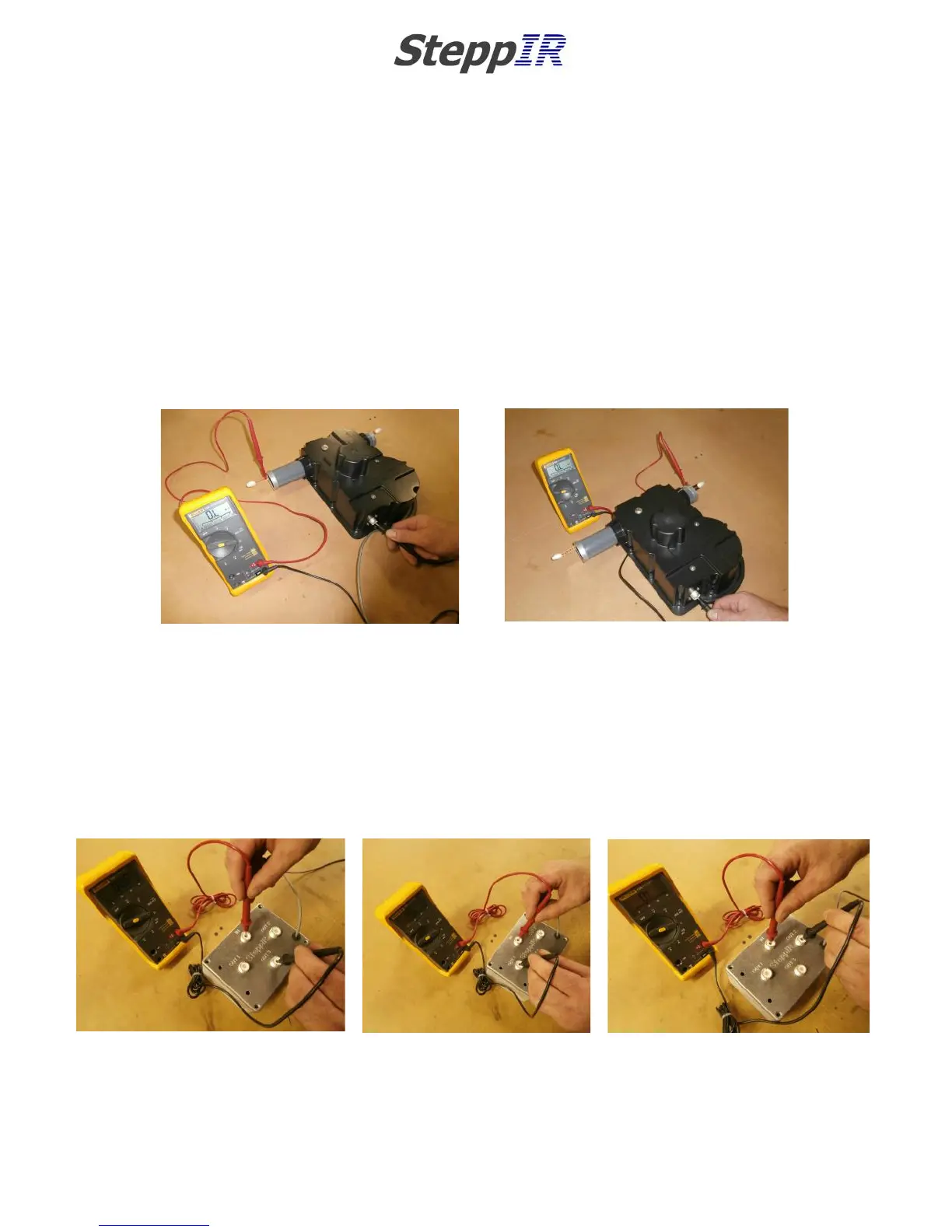
13. Measure the resistance on each of the three elements (Driven, Ref, D1) between the center
conductor of the SO-239 on the EHU and EACH of the two copper tape elements on that
same EHU as shown in figure 5.31 and Figure 5.32. The Driven element should measure a
very low resistance of 3 ohms or less (has Continuity) while REF and D1 should measure as
an OPEN circuit (a very high resistance value, NO continuity). Note that when an element
is in the “driven” mode there will be continuity between the copper tapes on that EHU.
Rest assured it is only a short at DC and not RF frequencies, this is intended by the design
of the balun. These tests confirm that the Driven element is acting as a driven and that
REF and D1 will act as passive elements on 6-20m.
CHAPTER FIVE
SECTION 5.3
WIRING THE CONNECTOR JUNCTION BOX (continued)
WIRING TEST (continued)
14. The next test is to verify the Coax Switch Box has selected the proper coax line.
15. On the antenna Coax Switch Box, use the ohm meter to verify there is very low resistance, less
than 3 ohms (has Continuity) between the center conductor of the SO -239 connector labeled
“IN” and the center conductor of the SO-239 labeled “OUT3” as shown in figure 5.33. Verify
that an Open circuit (very high resistance reading, No Continuity) exists between the center pin
of the “IN” coax connector and “OUT1” center pin as shown in figure 5.34 and also between
“IN” and “OUT2” coax connector center pins as shown in figure 5.35.
16. If any of these tests fail, Stop, Push Retract, Disconnect the controller cable and check your
wiring and correct any mistakes. Then restart the test procedure at the beginning.
17. If all the tests results are good from step 15, DISCONNECT the control cable.
FIG. 5.31
FIG. 5.32
FIG. 5.33
FIG. 5.35
FIG. 5.34