22 |DHF-C www.stiebel-eltron.com
INSTALLATION
Safety
INSTALLATION
7. Safety
Only a qualified contractor should carry out installation, commis-
sioning, maintenance and repair of the appliance.
7.1 General safety instructions
We guarantee trouble-free function and operational reliability only
if original accessories and spare parts intended for the appliance
are used.
!
Material losses
Observe the maximum inlet temperature. Higher tem-
peratures may damage the appliance. You can limit the
maximum inlet temperature by installing a central ther-
mostatic valve.
7.2 Instructions, standards and regulations
Note
Observe all applicable national and regional regulations
and instructions.
Protection rating IP 24 (splashproof) can only be guaranteed with
a correctly fitted cable grommet.
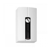
8. Appliance description
8.1 Standard delivery
The following are delivered with the appliance:
- Wall mounting bracket
- Installation template
- 2 twin connectors
- Cross-piece
- Tee
- Flat gaskets
- Strainer
- Plastic profile washer
- 2 cover guides (for installation on finished walls)
8.2 Accessories
Taps/valves
- MEKD - kitchen pressure tap
- MEBD - bath pressure tap
Plug G½A
The plugs are required if you use any taps other than the pressure
taps for finished walls recommended in the accessories.
Installation set for finished walls
- Solder fitting - copper pipe for solder connection Ø12mm
- Compression fitting - copper pipe
- Compression fitting - plastic pipe (suitable for Viega: San-
fix-Plus or Sanfix-Fosta)
Universal mounting frame
Mounting frame with electrical connections.
Load shedding relay (LR 1-A)
The load shedding relay for installation in the distribution board
provides priority control for the instantaneous water heater when
other appliances, such as electric storage heaters, are simultane-
ously being operated.
9. Preparations
9.1 Installation site
!
Material losses
Install the appliance in a room free from the risk of frost.
Always install the appliance vertically and near the draw-off
point.
The appliance is suitable for undersink and oversink installations.
Note
Mount the appliance on the wall. The wall must have
a sufficient load-bearing capacity.
9.2 Water installation
- Never operate with preheated water.
- A safety valve is not required.
Flush the water line thoroughly.
Ensure that the flow rate for switching on the appliance is
achieved (see chapter "Installation/ Specification/ Data
table", On). Increase the mains water pressure if the re-
quired flow rate is not achieved with the draw-off valve fully
opened.
Taps/valves
Use appropriate pressure taps. Open taps are not permitted.
Thermostatic pressure valves must be suitable for hydraulically
controlled instantaneous water heaters.
Note
Never use the shut-off valve in the cold water inlet to
reduce the flow rate. It is intended for shutting off the
appliance.
Permissible water pipe materials
- Cold water inlet pipe:
Galvanised steel pipe, stainless steel pipe, copper pipe or
plastic pipe
 Loading...