OPERATION
Menu structure
www.stiebel-eltron.com WPM 3| 25
WW PWM
This is where you determine the percentage output with which
HS2 will provide DHW heating. Adjustable from 0 to 100 %.
5.4.4 COOLING
COOLING
ON / OFF
COOLING MODE
PASSIVE COOLING
ACTIVE COOLING
Standard setting
COOLING STAGES
Here, the number of cooling stages is set. You can select 1-n heat
pumps.
COOLING LIMIT
If the current outside temperature falls below the temperature set
here, cooling is switched off.
COOLING CAPACITY
Here, the cooling capacity for HP types 3/3* and 5/5* is set.
ACTIVE COOLING
AREA COOLING
FLOW TEMPERATURE
FLOW TEMP HYSTERESIS
SET ROOM TEMPERATURE
DYNAMICS ACTIVE
DYNAMICS PASSIVE
FAN COOLING
FLOW TEMPERATURE
FLOW TEMP HYSTERESIS
SET ROOM TEMPERATURE
DYNAMICS ACTIVE
DYNAMICS PASSIVE
PASSIVE COOLING
AREA COOLING
FLOW TEMPERATURE
FLOW TEMP HYSTERESIS
SET ROOM TEMPERATURE
DYNAMICS PASSIVE
FAN COOLING
FLOW TEMPERATURE
FLOW TEMP HYSTERESIS
SET ROOM TEMPERATURE
DYNAMICS PASSIVE
The heat pump manager enables the cooling of individual appli-
ances (e.g. WPF M, WPF20-66 and WPL 13,18, 23 cool) as well
as appliances controlled in a cascade. Cooling is only possible in
conjunction with a buffer cylinder or low loss header.
The heat pump manager must be in SUMMER MODE. The changeo-
ver from heating mode to SUMMER MODE is subject to the outside
temperature and the SUMMER MODEparameter.
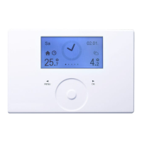
In addition, the analogue remote control unit with room temper-
ature sensor FE7 or the digital remote control unit FEK with room
temperature sensor and humidity sensor must be connected via
a CAN BUS.
Cooling mode with the FE7
The analogue remote control unit with room temperature sensor
FE7 is not equipped with dew point monitoring. It can therefore
only be used in conjunction with fan convectors or ceiling cassettes
with condensate drain.
Cooling mode with the FEK
The digital FEK remote control unit is equipped with dew point
monitoring, and can be used with area heating systems (e.g. un-
derfloor/wall heating systems, cooling ceilings etc.).
In passive cooling mode, the source pump and buffer charging
pump start when there is a cooling demand. In the active cooling
mode, the compressor is also operational.
!
Appliance and system damage
Wiring information: The previous solar circuit pump out-
put becomes the cooling output. The DHW flow sensor
at the bottom or the return sensor (sensor 1) becomes
the cooling flow sensor. Consequently, solar mode and
the heat metering function are then no longer available.

 Loading...


