www.stiebel-eltron.com WPM 3| 53
INSTALLATION
Troubleshooting
Fault list for multifunction assembly MFG
Fault display Reason for fault code being triggered Possible cause of fault / remedy
TO T VOR NHZ MFG The flow sensor of the electric emergency/booster heater in the MFG is faulty. Check the communication cable terminal or replace the
communication cable.
TO VOL HK MFG Incorrect communication with the MFG. Check the communication cable terminal or replace the
communication cable.
TO P HK MFG Incorrect communication with the MFG. Check the communication cable terminal or replace the
communication cable.
TO PU HK MFG Incorrect communication between heating circuit pump and MFG. Check the communication cable terminal or replace the
communication cable.
TO VALVE MFG Incorrect communication between 3-way diverter valve and MFG. Check the communication cable terminal or replace the
communication cable.
TO NHZ MFG Incorrect communication of the electric emergency/booster heater in the MFG. Check the communication cable terminal or replace the
communication cable.
TO MFG MFG timeout Check the communication cable terminal or replace the
communication cable.
ERR NHZ MFG The electric emergency/booster heater in the MFG is faulty. Check the communication cable terminal or replace the
communication cable.
ERR VALVE MFG Error 3-way diverter valve MFG. Check the communication cable terminal or replace the
communication cable.
ERR PU HZG MFG Error heating circuit pump MFG. Check the communication cable terminal or replace the
communication cable.
13.3 Fault message – sensor break
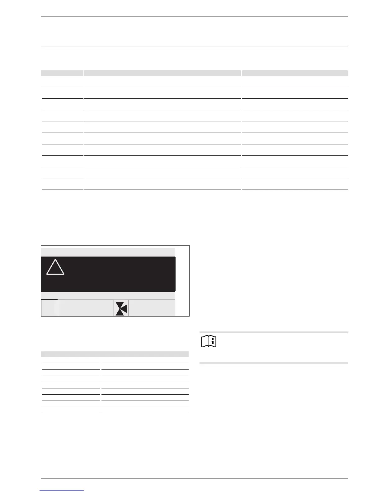
If the appliance registers a fault, this is clearly displayed with the
message shown below.
COMFORT MODE
!
SENSOR BREAK 70
SENSOR BREAK E 71
TUESDAY 25JUN 13 16:27 TIME
If more than one fault occurs, the most recent fault is always
shown.
Fault table
System fault Sensor
SENSOR BREAK E 70 Mixer sensor
SENSOR BREAK E 71 Source sensor
SENSOR BREAK E 72 Flow sensor
SENSOR BREAK E 73 Return sensor
SENSOR BREAK E 75 Outside temperature sensor
SENSOR BREAK E 76 DHW sensor
SENSOR BREAK E 77 HS 2 sensor
SENSOR BREAK E 80 Remote control
SENSOR BREAK E 129 Collector sensor
13.4 Heat pump-specific or hardware faults
See also chapter "Fault list".
13.4.1 The heat pump is not running
The heat pump is in standby mode.
Change the system over to programmed operation.
The power supply has been blocked; POWER-OFF is displayed.
Wait for the blocking time to elapse. The heat pump will au-
tomatically start up again.
There is no heat demand.
Check the set and actual values under the INFO menu item.
There may be an incorrect fuse rating.
See chapter "Specification / Data table".
Note
The heat pump can only be restarted after the fault has
been removed and the heat pump has been reset (heat
pump reset parameter).
Additional parameters available for system analysis:
- QUICK START: The quick start must only be carried out by our
customer support. The heat pump compressor is checked
during a quick start.
- RELAY TEST: Test for all relays in the heat pump manager.
13.4.2 The WPM display is not responding to entries
Isolate the heat pump from the power supply.
Restart the system.
If an ISG is installed, the WPM must have completely started
up before you reconnect the ISG power supply.
 Loading...


