www.stiebel-eltron.com WPM 3| 33
INSTALLATION
Installation
Insert the plugs supplied as follows into the WPMS 3 to provide
complete assignment:
X11 Low voltage
1
2
3
4
5
6
7
8
9
10
Heat pump flow sensor
Earth
Heat pump return sensor
Earth
PWM output
DHW cylinder sensor
DHW sensor bottom, in the case of solar connection
Flow sensor, in the case of cooling
Sensor, heat source 2
Collector sensor, in the case of solar connection
Outside temperature sensor
X12 Low voltage
1
2
Earth
Source sensor
X13 Low voltage
1
2
Earth
Mixer flow sensor
X14 Low voltage
1
2
3
Remote control
Earth
Remote control
X15 Low voltage
1
2
3
4
BUS high
BUS Low
BUS Earth "–"
BUS "+"
X20 Power supply voltage
1
2
3
4
5
Mixer circuit pump
Source pump
L' Power supply utility enable signal (must be connected)
Solar circuit pump / cooling output
N
X21 Power supply voltage
1
2
Mixer open
Mixer close
X22 Power supply voltage
1
2
3
4
5
6
7
8
9
10
N
L
L* (voltage input for relay outputs)
DHW circulation pump
Buffer cylinder charging pump 1
Buffer cylinder charging pump 2
DHW charging pump
Heating circuit pump 1
Heat source 2 (floating contact)
Heat source 2 (floating contact)
10.5 Sensor installation
10.5.1 Contact sensor AVF 6 (included in the pack supplied)
Connect an additional return sensor in combination with the
following heat pump types:
- WPL 13 E/cool
- WPL 18 E/cool
- WPL 10 I
- WPL 10 AC(S)
- WPL 15-25 AC(S) (only in combination with a buffer cylinder)
- WPL 08-22 (S) Trend (only in combination with a buffer
cylinder)
- WPL 07-17 ACS classic (only in combination with a buffer
cylinder)
Note
For spread control and heat metering with the
WPL07-17ACSclassic in conjunction with the HM(S)
(Trend) hydraulic module, observe the operating and
installation instructions for this module.
For systems without a buffer cylinder
Fit the sensor in the heating circuit return as a contact sensor
and if necessary, downstream of any overflow valve installed.
For systems with a buffer cylinder
Fit the sensor as a return temperature sensor in the buffer
cylinder.
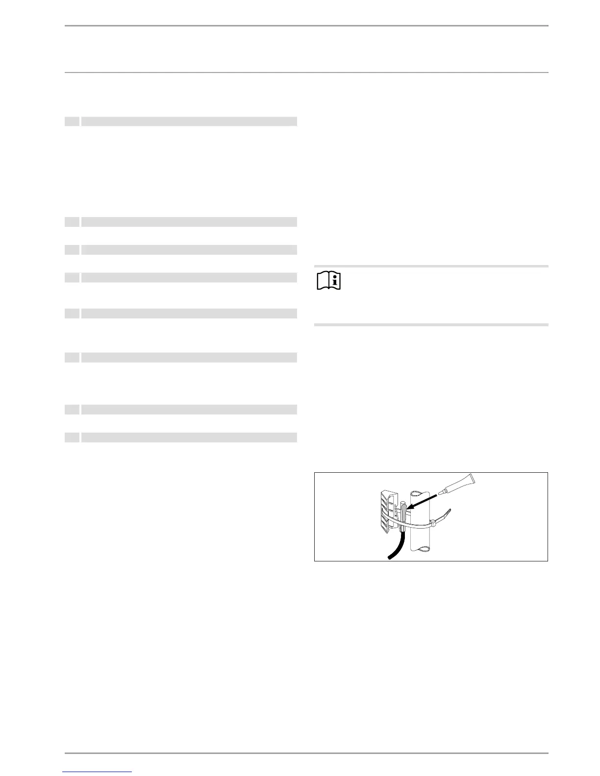
Installation:
The electrical connection is made at the user interface, specifically
at the “T/Buffer” terminal.
26�03�01�1431
Clean the pipe.
Apply heat conducting paste.
Secure the sensor with a cable tie.
 Loading...


