www.stiebel-eltron.com WPM 3| 35
INSTALLATION
Commissioning
10.8 Internet Service Gateway ISG
The Internet Service Gateway ISG enables you to operate the heat
pump in your local home network and via the internet when on
the go. Connect the Internet Service Gateway to terminals H, L,
and to terminal block X2 of the appliance.
The ISG power supply is not provided via the heat pump.
Also observe the ISG operating instructions.
11. Commissioning
Only qualified contractors may carry out any adjustments to the
heat pump manager (see list in the chapter "Setting parameters"),
commission the appliance and instruct the system user in its use.
Commissioning must be carried out in accordance with these op-
erating and installation instructions and the operating and instal-
lation instructions of all components belonging to the heat pump
system. Our customer support can assist with commissioning,
which is a chargeable service.
A heat pump system can comprise many different components.
A sound knowledge of the system function is therefore essential.
BUS initialisation
Connecting the BUS cable not only establishes the electrical con-
nection for system communication. As part of commissioning,
switching the BUS cable will also assign the appliance-specific
address required for switching the heat pump.
For the BUS connection it is essential that you carry out the steps
below in the order described:
Connect the WPM3 to the power supply.
Switch ON the MSM power supply (if installed).
Connect the heat pump to the power supply.
Set the system to standby mode
to prevent an uncontrolled
heat pump start during the initialisation phase.
The DIAGNOSIS/SYSTEM menu under BUS SUBSCRIBER displays
all connected BUS subscribers and their current software versions.
If an MSM is installed, this must be the first appliance to be
connected to the WPM3 via the BUS cable.
The DIAGNOSIS/SYSTEM menu under BUS SUBSCRIBER displays
the MSM and its current software version.
After completing initialisation, use the DIAGNOSIS/SYSTEM menu
under HEAT PUMP TYPES to check if all connected heat pumps are
being displayed.
Heat pump modules
The control panel for each heat pump provides space for the con-
nection of two 3-core BUS cables, i.e. the BUS cable between the
heat pumps is wired in parallel.
Sequence required when installing the heat pumps
Note
Heat pumps designed to heat DHW must always be in-
itialised first. The remaining heat pumps can then be
connected in any order.
All necessary sensors must be connected before the voltage is
connected to the WPM3.
Any sensors connected later will not be recognised by the WPM3.
Example: No DHW parameters, programs or temperatures are
displayed if the DHW cylinder sensor was not connected during
commissioning. No values can therefore be programmed for these
parameters.
If initialisation was carried out incorrectly, all IWS must be reset,
in other words, reinitialised.
The entire heat pump system will be shut down if the BUS cable
between the WPM3 and the heat pump is interrupted.
System configuration via the parameter settings (see list in
chapter "Setting parameters").
The list in chapter "Setting parameters" contains all settings for
the WPM3 function.
If the system is operating incorrectly, you should first check the
parameter settings in the list.
Reset options IWS
Reinitialising the IWS
Carry out this reset if commissioning or system initialisation failed.
To do so, proceed as follows:
Switch OFF the WPM3 power supply.
Switch OFF the MSM power supply (if installed).
Switch OFF the heat pump power supply.
Disconnect the BUS.
Switch the heat pump power supply back ON.
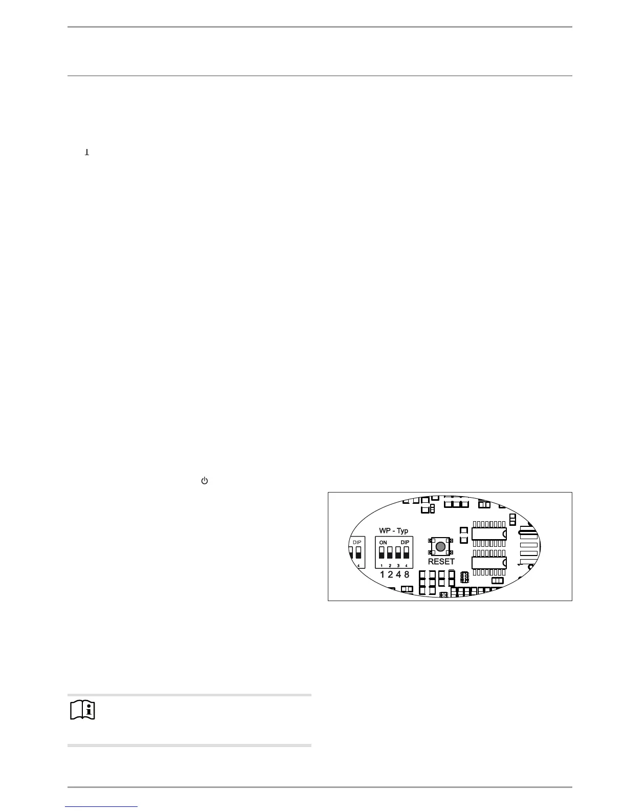
Hold down the reset button until the two outer LEDs con-
stantly illuminate and then go off again.
Release the reset button. The IWS has now been reset and is
ready for renewed initialisation.
 Loading...


