30 | WPM 3 www.stiebel-eltron.com
INSTALLATION
Installation
10.4 Electrical connection
10.4.1 General
DANGER Electrocution
Carry out all electrical connection and installation work
in accordance with national and regional regulations.
DANGER Electrocution
Only use a permanent connection to the power supply.
Ensure the appliance can be separated from the power
supply by an isolator that disconnects all poles with at
least 3 mm contact separation. This requirement can be
met with contactors, circuit breakers, fuses/MCBs, etc.
Note
The specified voltage must match the mains voltage. Ob-
serve the type plate.
When connecting the power, observe the relevant electrical
connection diagram.
The supply voltage at terminal L and the phase L' – switched by
the power supply utility – must be routed via the same residual
current device, as they share a neutral conductor in the WPM3.
Ensure that L and L' are in phase.
Disconnect all heating system poles from the mains power
supply before installation.
No fuses/MCBs for connected consumers are provided in the
WPM3 or in the wall mounting enclosure. A fuse/MCB for con-
nected consumers may be connected in series via terminal L* or
pumps L (see also heat pump connection diagram).
Circulation pumps and mixers
When making these connections, observe the maximum relay
capacity (2 A/250 V AC) and the maximum controller capacity
(10 A/250 V AC).
The DHW circulation pump relay output can be used for various
purposes, subject to the parameter settings.
!
Material losses
Only connect energy efficient circulation pumps ap-
proved by us.
If energy efficient circulation pumps are used that have
not been approved by us, use an external relay with a
breaking capacity of at least 10A/250VAC or our WPM-
RBS relay set.
The following energy efficient circulation pumps have been ap-
proved by us for direct connection to the heat pump manager:
Part no.:
UP 25/7.0 E 232942
UP 25/7.5 E 232943
UP 25/7.5 PCV 235949
UP 30/7.5 E 233947
WPKI-HK E 233602
WPKI-HKM E 233603
10.4.2 Electrical connection WPMW 3
The cable entries in the wall mounting enclosure are suitable for
rigid and flexible cables with an outside diameter of between
6mm and 12mm.
!
Material losses
The BUS cables, power cables and sensor leads must be
installed separately.
Mains and low voltage power are routed separately in the wall
mounting enclosure.
Route the low voltage leads into the left and right of the wall
mounting enclosure from below.
Route the power cables into the inlet ducts above the junc-
tion box.
When connecting the power supply, ensure the earth con-
ductor is correctly connected. Secure all cables to the wall
immediately below the wall mounting enclosure using cor-
rect strain relief fittings. The red wedges supplied are de-
signed to secure the cables inside the enclosure.
Check the function of the strain relief fittings.
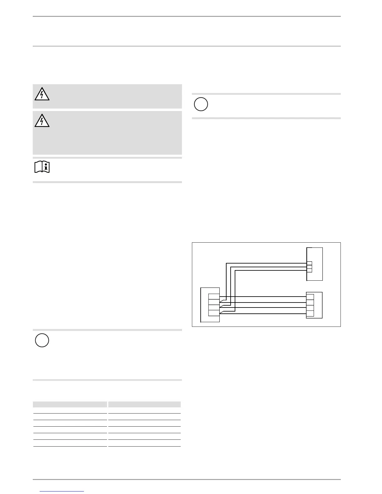
Connecting BUS cables
Install a J-Y (St) 2 x 2 x 0.8mm² cable as the BUS cable to the
heat pump.
A3
A2
11 1213 14
H L - +
A1
X2
4321
26�04�01�0066
A1 WPMW 3
A2 Programming unit
A3 Heat pump
 Loading...


