www.stiebel-eltron.com WPM 3| 31
INSTALLATION
Installation
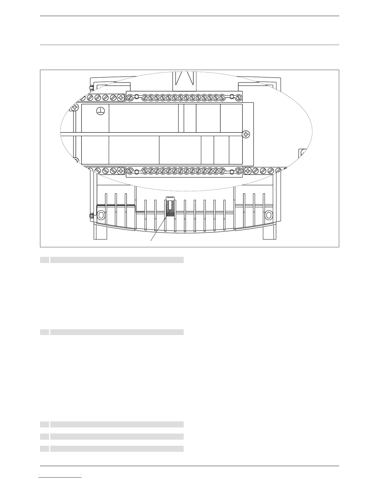
Connection array WPMW 3
1 2 3 4 5 6 7 8 9 10 11 12 13 14 15 16
N
PE
X5
X1
X2
X4
X3
Mains N
Mains L
PS L'
Pumps L
Buffer 1
Buffer 2
Source
Heat 1
Heat 2
DHW
DHW circ.
HS2
HS2
Mixer +
Mixer –
Solar/cooling
Outside
Flow
Return
DHW
HS2
Source
Mixer
PWM impulse
1
3
BUS H
BUS L
BUS –
BUS +
Sensor 1
Sensor 2
FE 7
1
1 2 3 4 5 6 7 8 9 10 11 12 13 14 15 16
26�03�01�0243
1 Wedge
X1 Power supply voltage
1
2
3
4
5 - 6
7
8 - 9
10
11
12 - 13
14
15
16
N
L
L' Power supply utility enable signal
Pumps L (voltage input for relay outputs)
Buffer cylinder charging pumps
Source pump
Heating circuit pumps
DHW charging pump
DHW circulation pump
Heat source 2
Mixer open
Mixer close
Solar circuit pump / cooling output
X2 Low voltage
1
2
3
4
5
6
7
8
9
10
11
12
13
14
15
16
Sensor outside temperature
Sensor, heat pump flow temperature
Sensor, heat pump return temperature
Sensor, DHW temperature
Sensor, heat source 2
Sensor heat source temperature
Sensor, mixer flow temperature
PWM output
Terminal 1 of the FE7 remote control
Terminal 3 of the FE7 remote control
BUS high
BUS Low
BUS Earth "–"
BUS "+"
DHW sensor bottom, in the case of solar connection
Flow sensor, in the case of cooling
Collector sensor, in the case of solar connection
X3 Earth
X4 N
X5 PE
 Loading...


