www.stiebel-eltron.com WPM 3| 29
INSTALLATION
Installation
26�04�01�0401
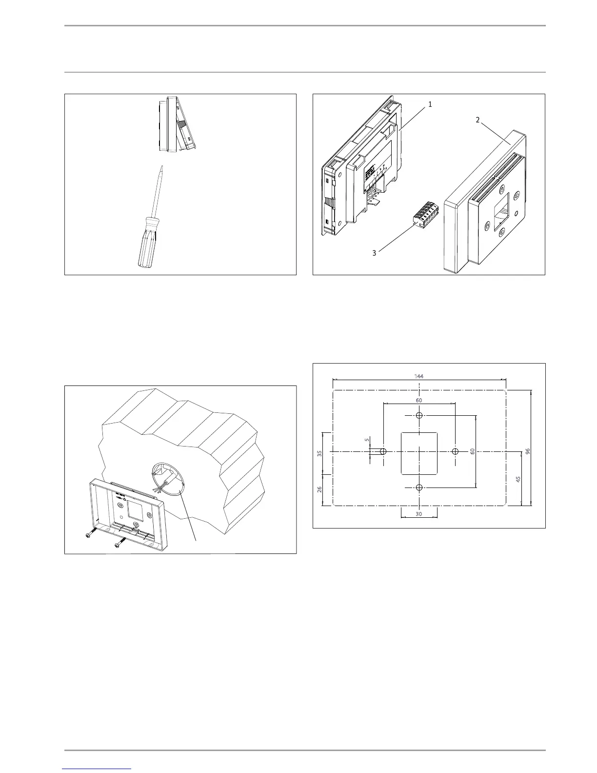
Reset the snap-in tab found in the opening on the underside
of the wall mounting enclosure. Press the snap-in tab with a
screwdriver.
The BUS cable must protrude 20 to 30cm out of the wall to allow
installation. For securing to a wall we recommend using a flush
box, which can hold this part of the BUS cable. Make sure that
the screws supporting the flush box are arranged either vertically
or horizontally opposite one another. The chapter "Installation
options" describes installation without a flush box.
26�04�01�0429
1
1 Flush box
Secure the wall mounting enclosure to the flush box using
the screws provided.
26�04�01�0399
2
1
3
1 Programming unit
2 Wall mounting enclosure
3 6-pole socket plug
10.3.1 Installation options
If you are not using a flush box you will have to drill four holes
(Ø5mm) for securing the wall mounting enclosure.
96
144
45
60
60
30
5
35
26
26�04�01�0400
When routing the BUS cable, be careful not to damage the cable
when drilling the fixing holes.
In the area around the power cable entry (behind the wall mount-
ing enclosure), a reservoir needs to be made to support 20 to
30cm of data cable.
 Loading...


