39FS 240 C, FS 260 C, FS 360 C, FS 410 C, FS 460 C-M
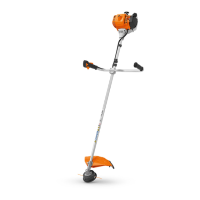
6. Ignition system
Exercise extreme caution while
carrying out maintenance and repair
work on the ignition system. The
high voltages which occur can
cause serious or fatal accidents.
Troubleshooting on the ignition
system should always start with the
spark plug, b 3.5
– Remove drive tube assembly,
1-point antivibration system,
b 12.1, 4-point antivibration
system, b 12.2
– Remove clutch housing, b 4.1
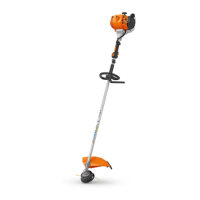
The electronic ignition system
basically consists of an ignition
module (1) and flywheel (2).
The ignition module accommodates
all the components required to
control ignition timing. There are
two electrical connections on the
coil body:
1. High-voltage output with
permanently installed ignition
lead.
2. Permanently installed lead with
lug for the short circuit wire
1
5904RA096 TG
2
Testing of the ignition module is
limited to a spark test. A new ignition
module must be installed if no
ignition spark is obtained (after
checking that the wiring and stop
switch are in good condition).
6.1 Ignition timing
Ignition timing is fixed and cannot
be adjusted during assembly work.
Since there is no mechanical wear
in these systems, ignition timing
cannot get out of adjustment during
operation.
6.2 Ignition module
– Remove shroud, b 5.4
– Unplug the spark plug boot
– Remove drive tube assembly,
1-point antivibration system,
b 12.1, 4-point antivibration
system, b 12.2
: Remove screw (1) and pull
lead (2) of the ignition module out
of the guides (arrows)
1
2
5904RA097 TG
– Detach short circuit wire and
cable holder from engine,
b 6.6.2
So that the air gap between ignition
module and flywheel can be set
using setting gauge 0000 890 6400
during installation, the clutch
housing must be removed.
– Remove clutch housing, b 4.1
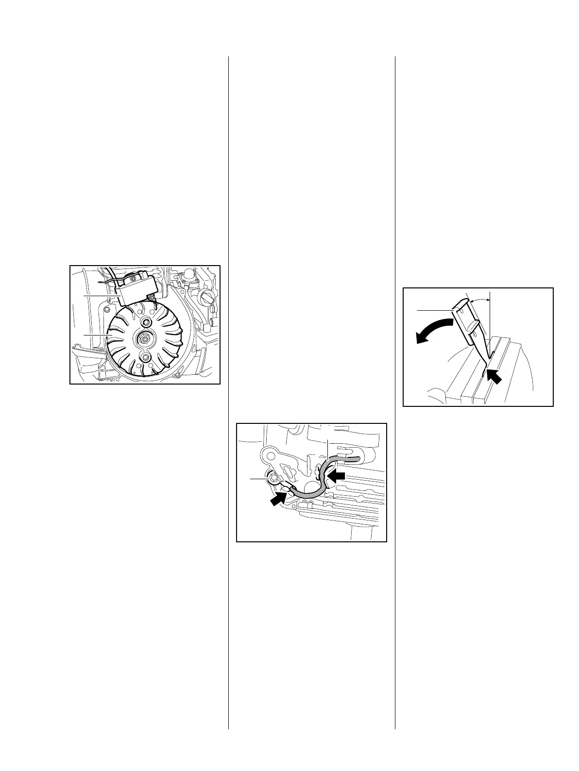
Alternatively, setting gauge
0000 890 6400 can be used to set
the air gap between ignition module
and flywheel with the clutch housing
installed. To do this, the gauge must
be bent one time.
: Clamp the measuring
tongue (arrow) in a vise and bend
the grip toward the measuring
tongue until the grip (1) is at an
angle of a = 30° relative to the
measuring tongue
1
5904RA334 TG
a

 Loading...