SatLink VSAT User Guide
Publication no. 101557
Copyright © 2009 – STM Group, Inc.
Page 128 (160)
Appendix F. ODU Installation
The ODU comprises the antenna with feed-horn and mounting structure, and a transceiver that contains
the LNB integrated with OMT, TX-reject filter, and the transmitter (BUC). If the STM SatLink
4033/4035 transceiver is not used, the OMT, LNB and BUC may be supplied as two or three separate
units. Two cables with F-connectors, one for TX and one for RX are connecting the ODU to the IDU.
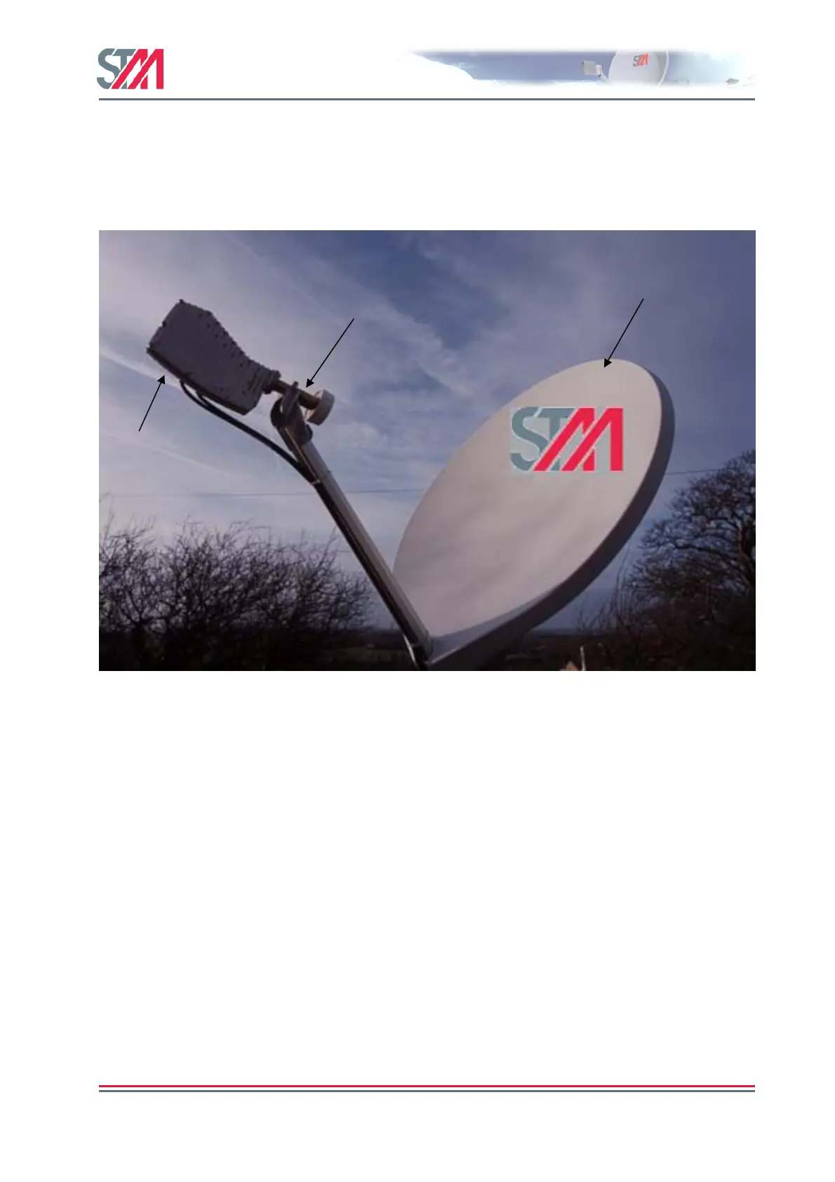
Figure 44: STM SatLink 4033/4035 Configuration
F.1 Assembly of SatLink 403x Transceiver to Feed Horn
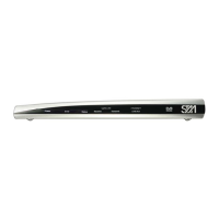
The STM SatLink 403x is supplied with 6 pieces of UNC 6/32 for connection to the antenna flange. The
parts are shown in the picture below. Please refer to Appendix G for information of how to connect the
STM SatLink 403x to antenna feed horn interfaces with 6 or 8 M4 screws.
Transceiver
mounted
directly on
antenna
feed
Antenna
Feed Horn
Antenna
Reflector