SatLink VSAT User Guide
Publication no. 101557
Copyright © 2009 – STM Group, Inc.
Page 134 (160)
Appendix G. SatLink 403x. Interfacing VSAT RX/TX
Antennas
The STM SatLink 403x series of Ku-band transceivers is configured with internal OMT as shown in
Figure 52 below. The output interface of the transceiver (C120) is therefore connected directly to the feed
horn of the antenna.
Figure 52: STM SatLink 403x output interface (Option A)
Antenna vendors offer different variants of the feed horn for their Ku-band RX/TX
antennas. The different options are listed below.
Option Feed Horn Interface
A C120 – 6 UNC screws
B C120 – 6 or 8 M4 screws
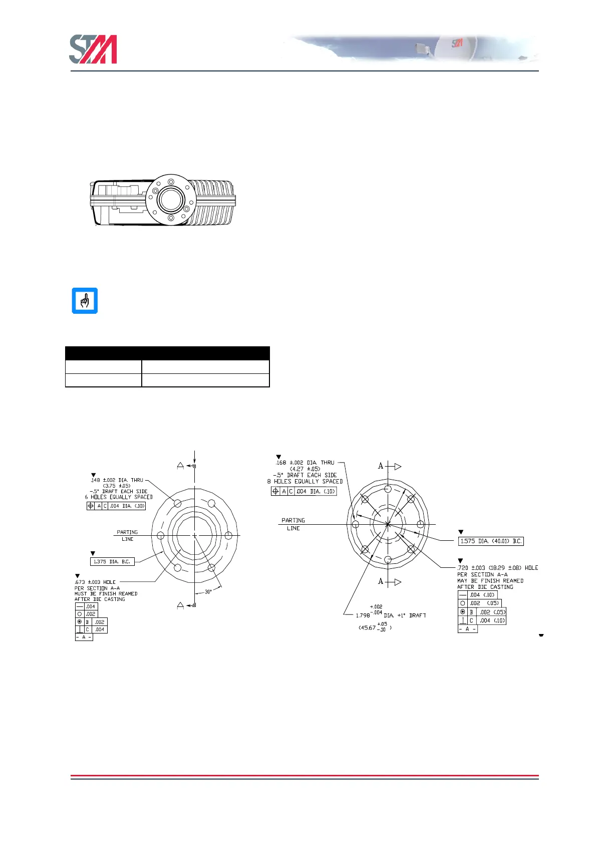
Option A interfaces the STM SatLink 403x directly while Option B requires an adaptor in order to fit the
STM SatLink 403x output interface. The hole patterns for option A and B are shown in Figure 53 and
Figure 54.
Figure 53: Option A antenna feed
hole pattern. Holes are distributed
equally at 60 degrees apart. STM
SatLink 403x fits directly to this
pattern using 6 UNC screws for
fastening.
Figure 54: Option B antenna feed hole pattern. Holes are
equally distributed at 45 degrees apart. Some versions have
only 6 holes. STM SatLink 403x fits on this pattern by means
of adapter STM SatLink 4901 (STM P/N 107268).