SatLink VSAT User Guide
Publication no. 101557
Copyright © 2009 – STM Group, Inc.
Page 23 (160)
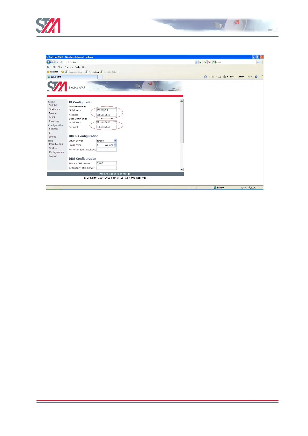
1) Click on the IP option in the SatLink VSAT home page.
Figure 19 : IP Configuration – LAN and DVB Interfaces
2) Enter the valid IP address and Netmask for the LAN and DVB interfaces.
3) Enable / Disable the DHCP server.
When enabled, the DHCP server will automatically be allocated all IP addresses in the VSAT LAN
subnet except the VSATs own IP address and addresses excluded manually.
4) Set the lease time for an IP address allocated to a host on the LAN.
5) Specify the number of IP addresses to be excluded from the available range of addresses defined by
the VSAT LAN subnet. The excluded range of IP addresses will be the upper range of the LAN
subnet.
6) Enter the IP address for the primary and secondary DNS servers to be used by the hosts on the VSAT
LAN.
7) Enable / Disable NAT for the VSAT.
8) Enable / Disable the TCP and HTTP PEP server.
9) Click Save button to save the configuration.
6.3 Line-UP Using Web Interface
Perform antenna and ODU installation and alignment as described in Appendix F and the initial
parameter configuration described in section 6.2 before proceeding with the line-up procedures described
here.
6.3.1 Antenna line-up
Set the alignment of the antenna to optimize the receive SNR. The RX SNR displayed in the graph on the
line-up page should appear as a green bar to ensure a stable reception of the forward link signal. If the bar
is yellow, the signal can be received correctly with low link margin, and if the bar is red, the signal level
is too low for error free reception.