10 MA_441-1-2_A1_180830_en
3
3.1
Disassembly of the machine
Before beginning with disassembling the main shaft, it is recommended to
record all parts on the shaft using a ruler in a straight line. If necessary, starting
at the front edge of the stand, measure the distances of the front and rear
bearing bracket using a calliper and write them down
(dimension a + b).
Disassembly of the front main shaft (Fig. 1 to Fig. 5)
This will save a lot of time during the assembly for calibration. (Fig. 4)
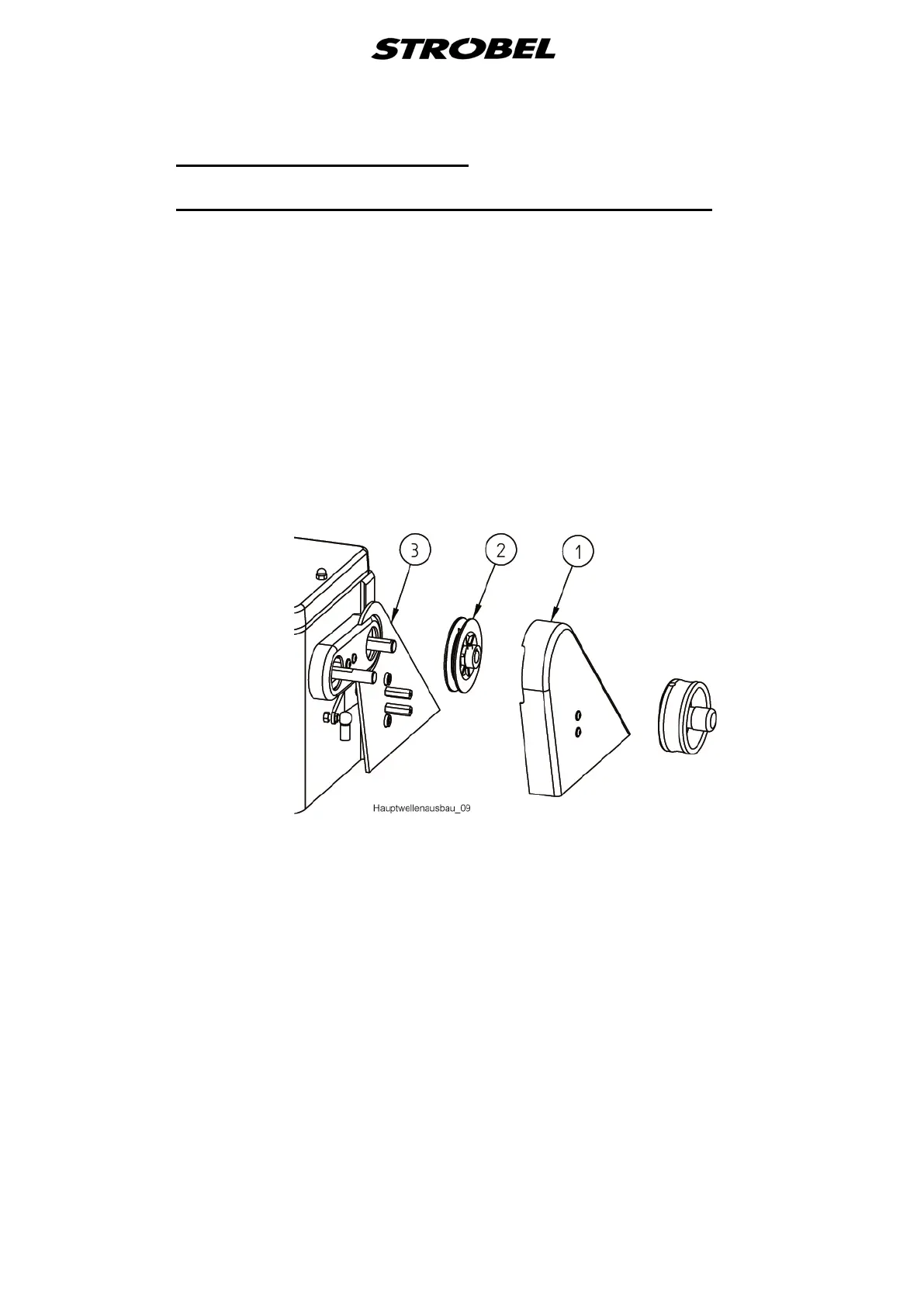
First of all, remove the right handwheel and then disassemble the belt guards in
the following sequence.
Cl. 441-1
The belt guard (1), the V-belt pulley (2) and the belt guard back wall (3). (Fig. 1)
Fig. 1
258.21.27
258.21.27
258.21.27
258.21.27