20 MA_441-1-2_A1_180830_en
4.5.6
Shifting the rear bearing bracket (N) (
Setting the rear bearing bracket
Fig. 4) or (7) (Fig. 9) changes the looper
transfer in the end positions. During pushing back, the looper goes closer to the
needle in the front and vertical looper position (without significant change of
height in rear position - ratio about 10:1); during pushing forward, the looper
distance to the needle becomes greater.
4.6
In case the socket (4) is removed, pull it in far enough so that the dimension of
8.8 ±0.1 (a) of (
Height adjustment of the feed cup
Fig. 14) results in mounted condition feed cup (5).
4.7
Cl. 441-1 (
Assembly of the front cup
Fig. 14)
During the assembly of the front cup on the machine, make sure that it is
mounted in horizontal position and by 0.1 mm lower in relation to the feed cup.
If there is a needle guard, the base of the needle channel has to be 0.1 mm
lower in turn than the top edge of the front cup.
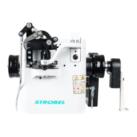
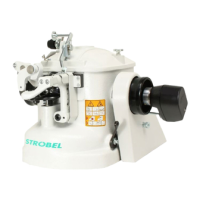
Cl. 441-2 (Fig. 11)
After the lid has been removed (1) (2x screws [2]), 2 threaded pins (4), which
have been inserted at 90°, can be loosened via the borehole in the flange (3)
and then the gearwheel (5) can be pulled out including the shaft (6).
Afterwards the retaining ring (7) can be taken from the bearing pin of the small
front cup and the front cup can be exchanged.
The assembly is done in reverse order.
To prevent damage to the feed cup teeth during a possible idling of the
machine, feed cup and front cup should be moved together only so far that
there still is a gap of 0.2 - 0.3 (b) mm between them. (Fig. 11)
The gap can be adjusted with threaded pin (4) and secured with threaded pin
(5). (Fig. 12)
Make sure that the front cup is mounted 0.1 mm lower in relation to the feed
cup. This can be adjusted by loosening the 2 threaded pins (8) from the needle
guard (9). (Fig. 11)