40 MA_VEB100-2-4-5_A5-3_230123_en.doc
3.9.3 Replacing the knife (Fig. 22 und Fig. 23)
A T T E N T I O N !
Switch off machine electrically!
To replace cylinder head screw (2), unscrew it (hold shaft (14) with open-
end wrench 5 mm).
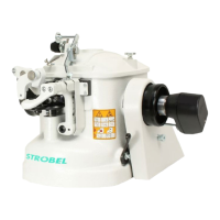
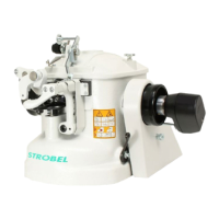
CAUTION: Do not hold onto the rotary knob (15) since the gearwheels can be
damaged!
The nose of knife (3) should sit in the shaft's groove to guarantee the right position for
the thread trimming.
- Turn the main shaft manually and check the trimming position. (Fig. 23)
3.10 Interval gear (Fig. 20)
Every second rotation, interval gear 1:2 lowers the material support arm (plunger) by
the value given by the interval stroke control.
3.10.1 Setting the interval gear (Fig. 20)
- Set the stitch depth until the desired stitching results are achieved.
- Turn the regulating button for intervals (4) Fig. 20 clockwise until the desired
interval stroke is achieved.