Do you have a question about the Stryker X7000 and is the answer not in the manual?
Details the one-year warranty on materials and workmanship and exclusions.
Specifies conditions like misuse, neglect, or unauthorized modifications voiding the warranty.
Defines the manual's purpose for electronics technicians and the Stryker Repair Team.
Outlines Stryker Endoscopy's responsibility for safety, reliability, and performance if repairs are authorized.
Informs about Stryker's right to improve the product and notify customers of significant upgrades.
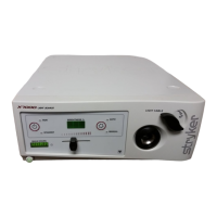
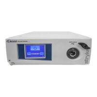
Lists the main components of the Stryker X-7000 Light Source system.
Advises returning malfunctioning units to Stryker or using qualified technicians for repairs.
Warns of risks from incorrect tool use and emphasizes repairs by specially trained personnel only.
Provides contact information and procedures for obtaining factory service during or after the warranty period.
Lists the essential tools and equipment needed for performing repair procedures.
Specifies the necessary qualifications and experience in electronics and multimeter operation for technicians.
Directs users to the Appendix for a list of necessary replacement parts for repairs.
Emphasizes understanding procedures and using adequate equipment for safety and reliability.
Details AC power cord requirements and recommends testing outlet grounding and polarity.
Specifies conditions for unit placement, operator accessibility, and ventilation.
Refers to the Operating and Maintenance Manual for detailed connection and wiring procedures.
Outlines steps to check unit operation after making power and signal connections.
A checklist for qualified Stryker personnel to complete and file in the DHR.
Identifies failure and repair codes for troubleshooting guidance.
Further identification of failure and repair codes for troubleshooting guidance.
Provides general guidance and notes on component replacement procedures.
Lists components and the required order of removal before accessing others.
Outlines specific procedures for removing and repairing individual components.
Details the steps required to safely remove the unit's console cover.
Step-by-step guide for replacing the control board, including calibration.
Instructions for replacing the lamp ballast assembly.
Procedure for replacing the AC inlet board.
Instructions for replacing the ballast fan assembly.
Procedure for replacing the bulb fan, noting both fans should be replaced if one fails.
Steps for removing and replacing the bulb board.
Steps for removing and replacing the shutter mechanism.
Guide for replacing the hot mirror component.
Procedure for replacing the motor mount assembly.
Instructions for replacing the motor.
Instructions for replacing the integrating rod.
Procedure for replacing the jaw handle.
Steps for replacing the potentiometer knob.
Guide for removing and replacing the front panel assembly.
Guide for removing and replacing the jaw assembly.
Procedure for replacing the power switch.
Steps for replacing the display board.
Detailed instructions for replacing fuses on the rear panel.
Lists basic electronics and oscilloscope skills required for electrical procedures.
Outlines procedures for unit alignment, calibration, burn-in, and hot strike.
Specifies skills needed, including electronics and current leakage testing.
Steps for reassembling the unit and verifying connections and components.
Procedure for performing a critical safety test to measure leakage current.
Procedure for performing a high-potential dielectric withstand voltage test.
Provides a visual diagram of the unit's assembly.
A list of part numbers and corresponding descriptions for the unit.
Lists other relevant documents, such as Manufacturing Assembly Procedures (MAPs).
| Brand | Stryker |
|---|---|
| Model | X7000 |
| Category | Lighting Equipment |
| Language | English |