18
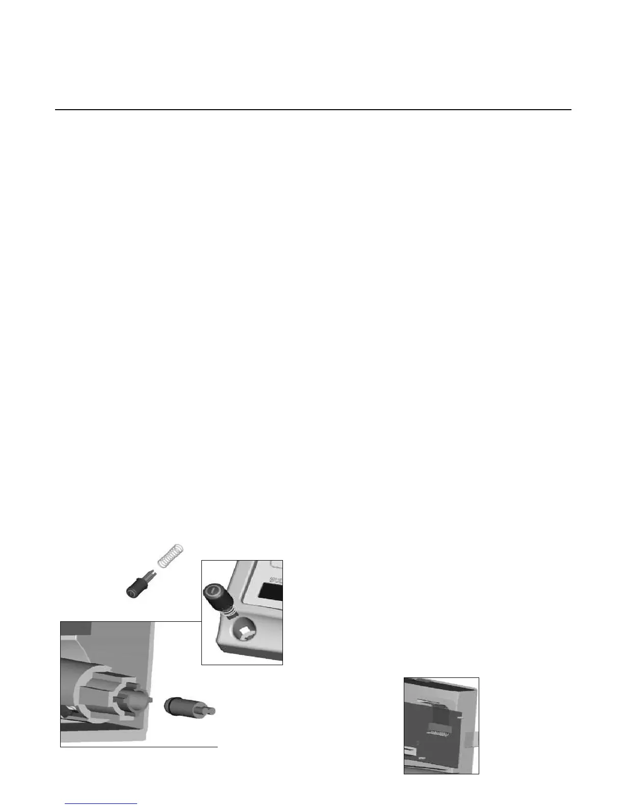
4.5.5 Power Switch Replacement
• Remove power cord and console cover (procedure 4.2).
• Remove the jaw knob and potentiometer
knob (procedures 4.5.1 and 4.5.2).
• Remove the front panel (procedure 4.5.3).
• Cut the zip tie over the cables.
• Disconnect wire harness from display board.
• Push in the two snap clips and push out the switch from
inside the console.
• Remove the LED and verify its operation.
• Replace the LED if necessary, inserting it to full depth
with the appropriate Allen wrench.
• Insert a new power switch.
• Reconnect the wire harness.
• Replace the zip tie, front panel, and console cover.
• Perform Electrical Current Leakage Test (procedure 6.3).
4.5.6 Display Board Replacement
• Remove power cord and console cover (procedure 4.2).
• Remove the front panel (procedure 4.5.3).
• Detach the flex cable from the display board (J1).
• Unclip the 6 front panel clips from the chassis.
• Remove the ESST ring cable from the display board.
• Remove the ribbon cable from the display board.
• Remove the power switch wire harness from the display
board.
• Remove the display board from the front panel clips.
• Replace the display board.
• Push the board onto the front panel clips.
• Reattach the power switch wire harness.
• Reattach the ESST ring wire harness.
• Reattach the front panel ribbon cable.
• Reinsert the front panel onto the chassis.
• Reattach the jaw handle and potentiometer knob (proce-
dures 4.5.1 and 4.5.2).
• Reinstall the console cover.
• Perform Electrical Current Leakage Test (procedure 6.3).
 Loading...