9
4.3 POWER SOURCE COMPONENTS
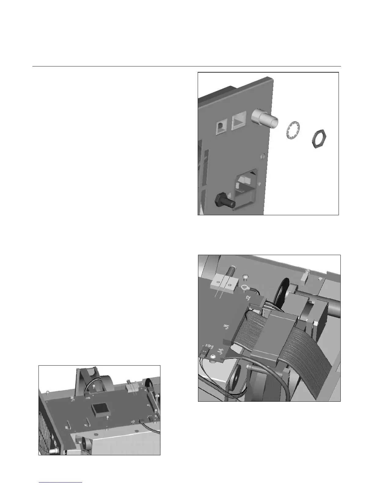
4.3.1 Control Board Replacement
Tools Required:
Basic Tool Kit
• Remove power cord and console cover (procedure 4.2).
• Disconnect connectors and attached wires.
• Remove the 5 screws attaching the control board to the
ballast.
• Unscrew the nut and washer on the BNC connector.
• Remove the old control board.
• Install a new control board with 4 screws.
• Reattach the connectors to their original locations,
including attaching the ground for the ribbon cable with
the 5th screw.
• Screw washer and nut onto BNC.
• Perform calibration (procedure 5.2).
• Reinstall the console cover.
• Perform Electrical Current Leakage Test (procedure
6.3).
 Loading...