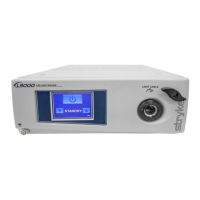
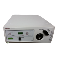
17
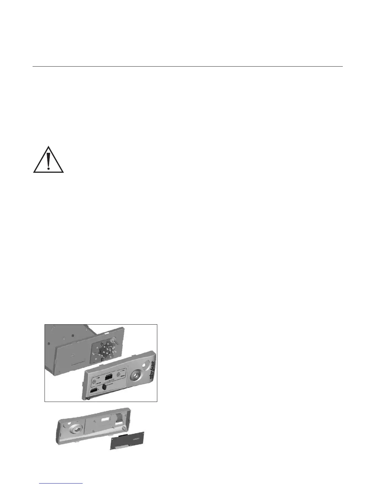
4.5.3 Front Panel Replacement
• Remove power cord and console cover (procedure 4.2).
• Remove the jaw knob and potentiometer knob (proce-
dures 4.5.1 and 4.5.2,).
CAUTION: DO NOT DAMAGE THE JAW INTERLOCK
CABLE WHEN REMOVING THE FRONT
PANEL.
• Disconnect the ribbon cable from the inside of the front
panel.
• Disengage the six tabs which hold the front panel onto
the chassis.
• Remove the jaw interlock cable from the display board.
• Remove the display board (procedure 4.5.6).
• Remove the power switch (procedure 4.5.4).
• Remove the ESST ring.
• Remove the front panel and replace with new panel.
• Replace all removed components.
4.5.4 Jaw Assembly Replacement
• Remove power cord and console cover (procedure 4.2).
• Remove the front panel (procedure 4.5.3).
• Remove the motor mount (procedure 4.4.5).
• Remove the ESST wire harness from the display board.
• Remove the 4 Phillips screws.
• Remove the jaw assembly and replace.
• Reinsert the 4 Phillips screws.
• Replace the ESST wire harness, motor mount, front
panel, and cover.
 Loading...