12
4.3.4 Ballast Fan Replacement
Tools Required:
Basic Tool Kit
NOTE: BOTH fans must be replaced if one fan malfunc-
tions.
• Remove power cord and console cover (procedure
4.2).
• Remove the black ribbon cable.
• Remove the fan wire harness assembly.
• Note the fan orientation.
• Remove the 2 nuts attaching the fan to the Chassis and
remove the sub-assembly.
• Remove the 4 screws from the fan mounts.
• Remove the malfunctioning fan(s) and replace. Ensure
the correct orientation.
• Reinstall the 2 fan mounts with the 4 screws.
• Reinstall the 2 nuts.
• Reinstall the black ribbon cable, fan wire harness assem-
bly, and console cover.
• Perform Electrical Current Leakage Test (procedure 6.3).
4.4 LIGHT SOURCE COMPONENTS
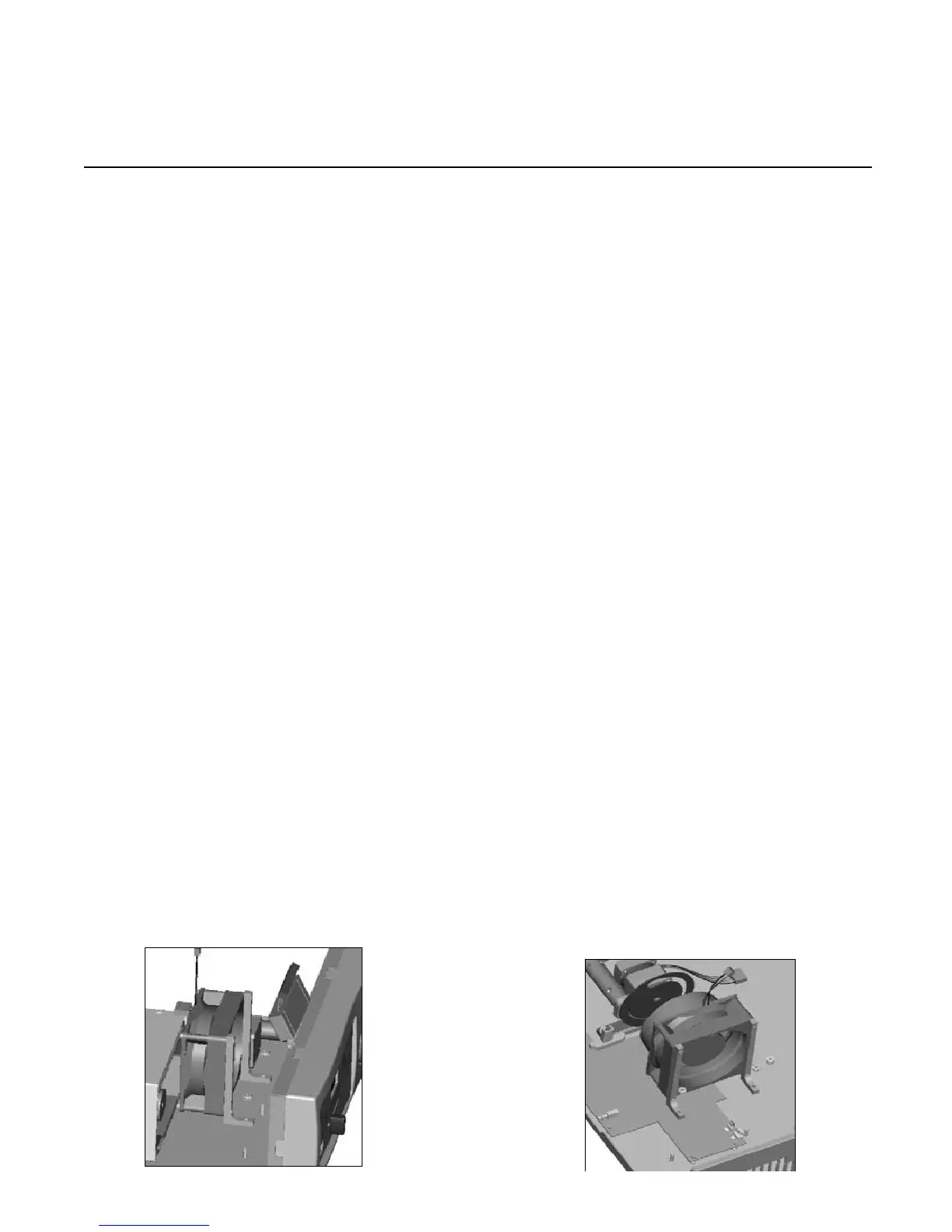
4.4.1 Bulb Fan Replacement
Tools Required:
Basic Tool Kit
NOTE: BOTH fans must be replaced if one fan malfunc-
tions.
• Remove power cord and console cover (procedure
4.2).
• Remove the bulb module.
• Detach the wire harness from the control board.
• Remove the 2 nuts attaching the bulb fan housing assem-
bly to the chassis.
• Note the fan orientation.
• Remove the 4 nuts attaching the bulb fan to the fan
mounts/fan ducts.
• Reinstall the new fan onto the mounts/duct with 4 bolts,
ensuring the correct orientation.
• Reinstall the fan assembly onto the chassis with 2 nuts.
• Reconnect the wire harness.
• Replace the bulb module and cover.
 Loading...