EasyManuals Logo

Stryker X7000 User Manual

Stryker X7000
31 pages
To Next Page IconTo Next Page
To Previous Page IconTo Previous Page
Page #27 background imageLoading...
Page #27 background image
23
7.0 Appendix
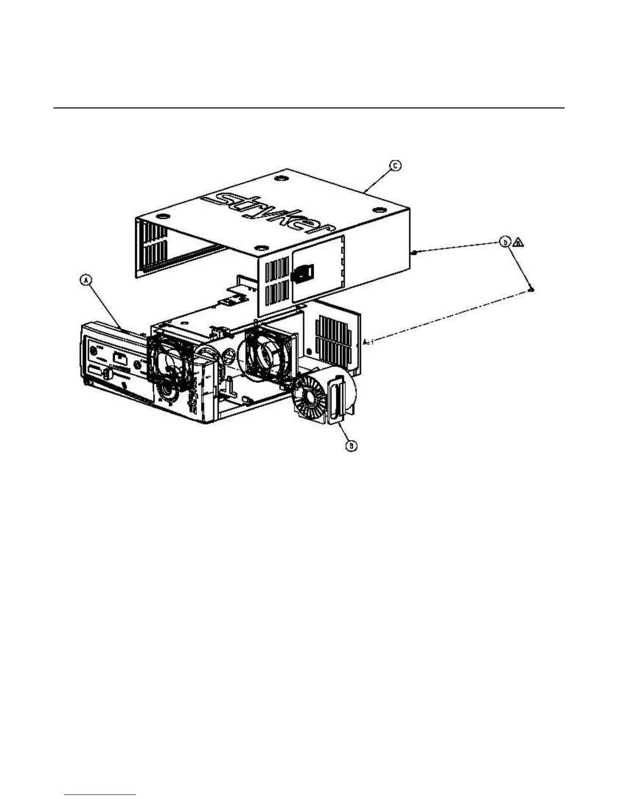
7.1 ASSEMBLY DIAGRAM
7.2 PARTS LISTING
A 105-199-584 ASSY, X-7000 BOTTOM TRAY
B 105-199-581 ASSY, X-7000 ELLIPTICAL BULB MODULE
C 105-199-678 ASSY, COVER, X-7000
D 105-193-198 SCREW, 6-32 X 0.25 PH EXT. SEMS
7.3 REFERENCE DOCUMENTS
• MAP 0337
NOTE: NONE OF THE IN-HOUSE MAPs (Manufac-
turing Assembly Procedures), QIPs (Quality
Inspection Procedures), SPECIALTY TOOLS,
JIGS, OR FIXTURES LISTED IN THIS MAN-
UAL ARE AVAILABLE FOR PURCHASE.

Questions and Answers:

Question and Answer IconNeed help?

Do you have a question about the Stryker X7000 and is the answer not in the manual?

Stryker X7000 Specifications

General IconGeneral
BrandStryker
ModelX7000
CategoryLighting Equipment
LanguageEnglish

Related product manuals