7
4.1 COMPONENT REPLACEMENT INSTRUCTIONS
Required skills:
Basic electronics techniques.
WA R N I NG : The incorrect use of any of the required tools
and techniques may risk damage to the
equipment or injury to the person carrying
out the procedure, subsequent operators, or
patient. Repairs should be made ONLY by
those that have been specifically trained in
the use of all pertinent equipment andtech-
niques.
The following instructions apply to the removal of compo-
nents from the X-7000. To remove a component for
replacement or repair will require the removal of certain
other components. Components must be removed in the
order listed in the following procedures.
The table in section 4.1.1 shows the order in which compo-
nents must be removed according to the basic physical
assembly of the X-7000. To remove a component for
replacement, or repair, begin with section 4.2 and proceed
accordingly to the appropriate section.
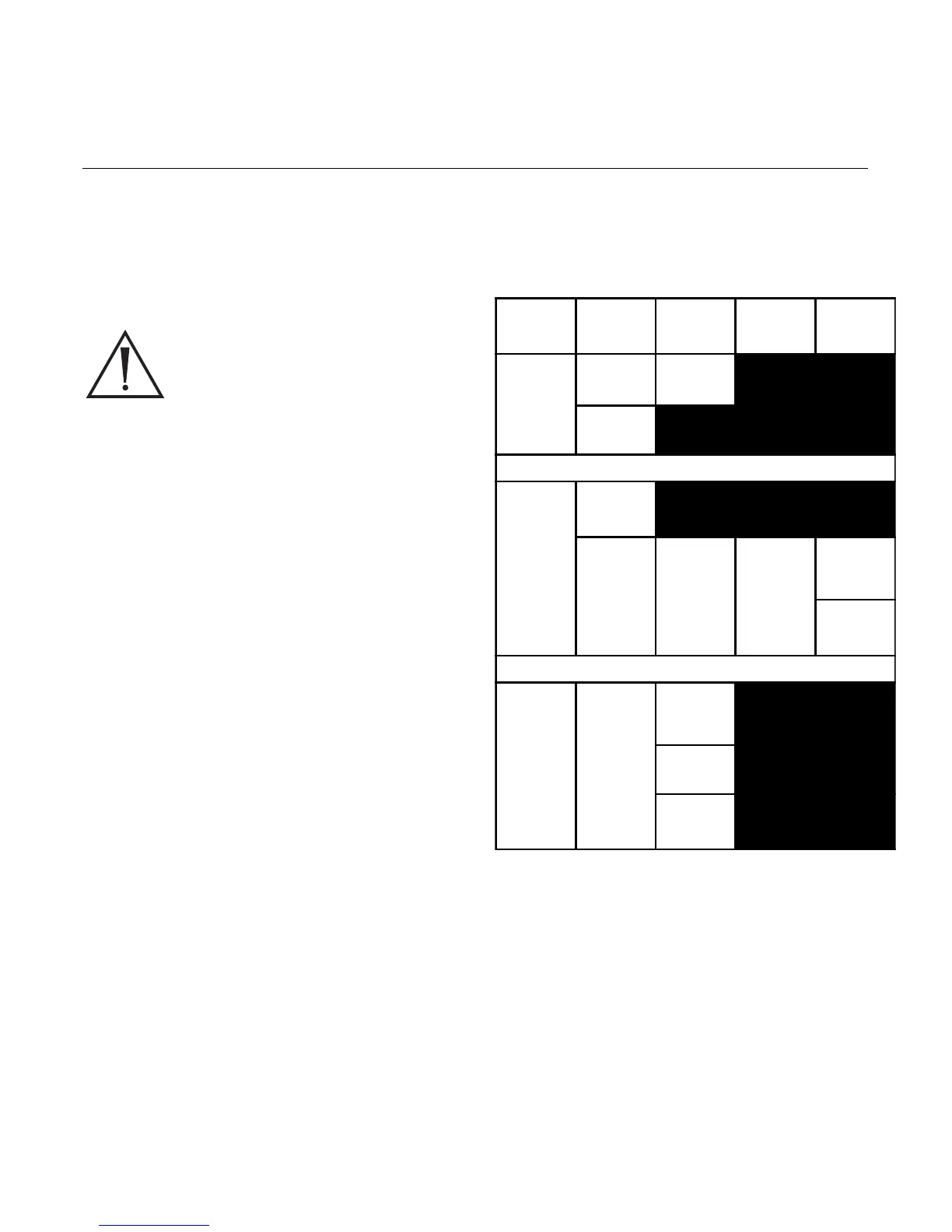
4.1.1 Component Removal Table
NOTE: All components in previous columns must be
removed before removing a component.
4.0 Component Removal and Repair
12 3 4 5
Control
Board
Ballast AC Inlet
Board
Ballast
Fan
Bulb,
Bulb Fan
Bulb
Board
Shutter Hot
Mirror
Motor
Mount
Assembly
Motor
Integrat-
ing Rod
Slide
Button,
Jaw Knob
Front
Panel
Power
Switch
Display
Board
Jaw
Assembly
 Loading...