89
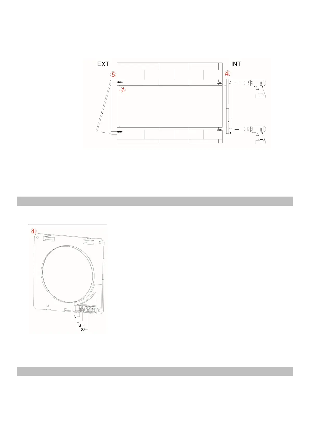
At the end of the electrical connection, fix the wires carefully in the fitted compartment, and screwt
he particular wall mounting (4i) into the wall, with the 4 screws provided, as in the image below.
3.2 DIRECT CONNECTION SOLO
Before proceeding with connection, make sure that the power supply cables (line and neutral) are
present in the area specially formed in the wall.
Extract the particular internal wall mounting (4i) and the tools
necessary for connecting the power supply network with the
stripped wires provided in the special compartment.
Connect, in an appropriate and safe manner, the network power
supply cables with those from the terminal block. Indications "N"
and "L".
Picture: Rear plate Interior wall-fixing (see wall-fixing)
3.3 CONNECTION WITH EXTERNAL SWITCH SOLO
It is also possible to switch the wall ON / OFF commands and select speed remotely.
 Loading...
