Installation
Size of drive wheel used on sweep depends on size of bin and unload system. A 10” wheel with 4:1
reducer comes standard for all 6” systems and for 8” systems in bins up to 34’ dia. A 17” wheel with 16:1
reducer comes standard for 8” systems in bins 36’ dia. and larger and for all 10” systems.
For attachment of 10” wheel, see Fig. 23. Loosely
bolt sweep auger to reduction wheel input shaft using
two 5/16 x 1-3/4” screws (J0570) and two 5/16” lock
nuts (J1010). Loosely bolt mounting bracket to sweep
backboard using two 3/8 x 1” screws (J0606), 3/8”
split lock washers (J1205) and 3/8” hex nuts (J1020)
as shown. Position wheel so it is perpendicular with
backboard and straight up and down. Tighten bolts
connecting shaft to auger, and bolts connecting
mounting bracket to backboard.
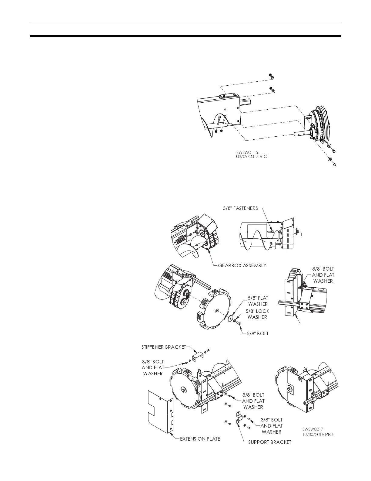
For attachment of 17” wheel, see Fig. 24. Slide gearbox assembly shaft into auger. On 8” system, secure
with 5/16 x 1-3/4” bolts and 5/16” lock nuts. On 10” system, secure with 3/8 x 2-1/4” bolts and 3/8” lock
nuts. NOTICE: Ensure gearbox is straight. Failure to do so may cause auger tube to break.
Bolt gearbox assembly to
backboard using 3/8 x 1” bolts, flat
washers and flange nuts. See Fig.
24.
Remove 5/8” bolt from gearbox
output shaft. Use it to attach drive
wheel as shown in Fig. 25.
Attach grain reclaim shield as
shown in Fig. 25 using 3/8 x 3/4”
bolts, flat washers.
Attach extension plate, support
bracket and stiffener bracket as
shown in Fig. 26 using 3/8 x 3/4”
bolts, flat washers.
NOTE: On reclaim shield there are
three holes in each of the three
sets of holes for mounting
extension plate. Use the middle
hole in each set.
NOTE: If bin has a stirring
machine, trim its down-augers to
avoid contact with sweep and 17”
wheel. Minimum clearance from
any object is 6”.