Installation
Incline
To aid in part identification during assembly of incline for 6” Sweepway, see Pages 58-59.
Installation of incline will depend on size of Sweepway system.
Instructions for 6” system start below. Instructions for 8” or 10”
systems are on next page.
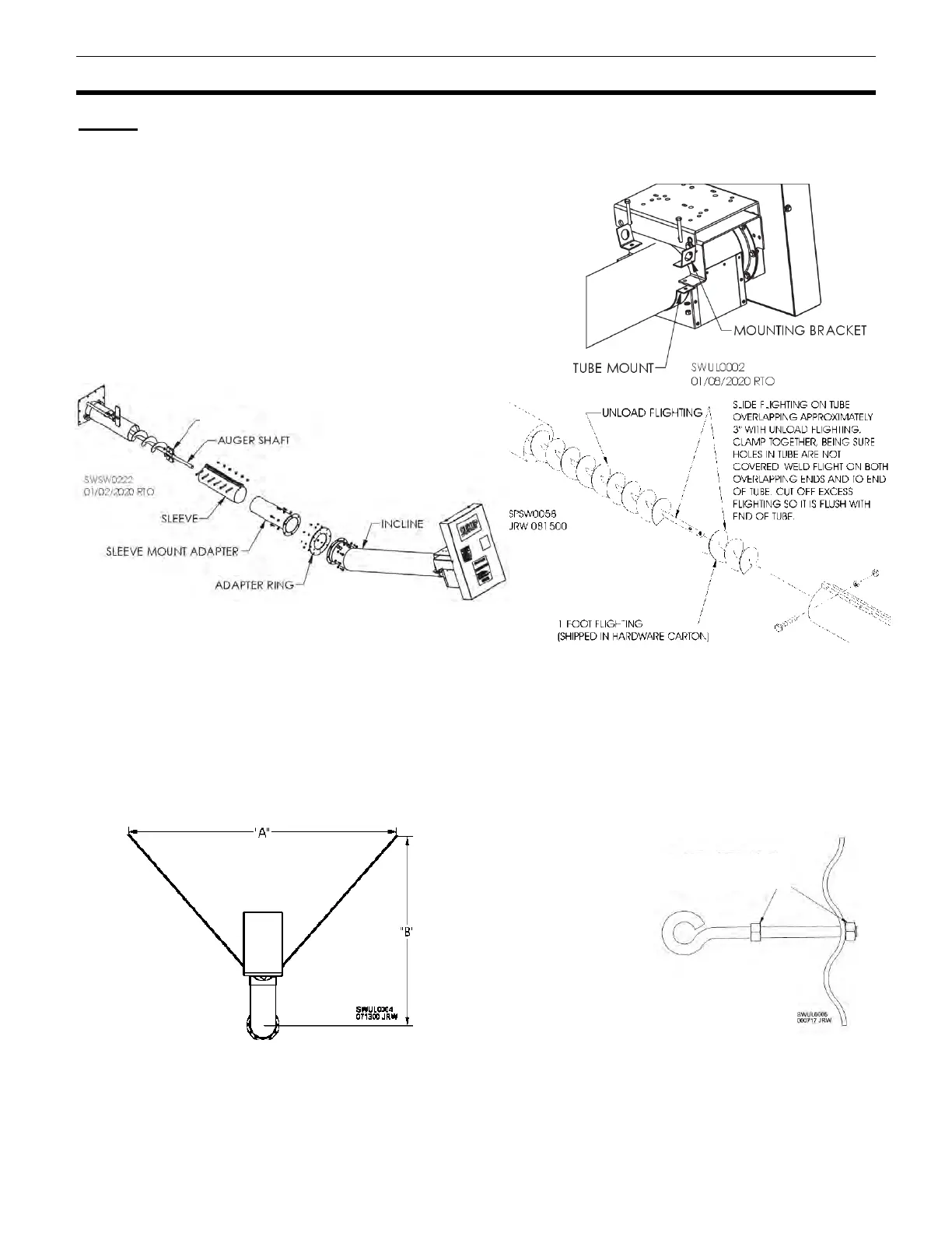
Remove bolts holding 6” system tube mount to incline tube.
Attach mounting brackets to incline using previously removed
bolts. See Fig. 30.
Remove flinger and auger shaft from unload auger. See Fig.
32. Weld 1’ section of flighting to unload auger. See Fig. 32.
Pull auger out of unload tube slightly. Slide sleeve, sleeve mount adapter and adapter ring over auger.
Temporarily support incline. Attach unload auger to shaft in incline using previously removed hardware.
Attach adapter ring to incline as shown in Fig. 31. Loosely attach sleeve and sleeve mount adapter as
shown.
Slide incline up to unload tube and tighten in place. Ensure inside square section of auger slides into
square shaft in center sump.
Remove outer belt shield and install belts. See Page 34 to tighten belts. Reinstall outer belt shield.
Remove two bin bolts spaced equidistantly from unload tube (“A” = 80-100") along seam between
second and third rings of bin sheets (“B” = 60-80"). See Fig. 33. Install eyebolts in place of bin bolts. See
Fig. 34.
Connect one end of each support chain to mounting bracket shown in Fig. 30 and other end to an
eyebolt. See Fig. 34. Tighten bolts.
INSTALL EYEBOLT WITH ONE NUT COMPLETELY THREADED
BEFORE PUTTING IN BIN WALL. START SECOND NUT ON
EYEBOLT, LEAVING ROOM TO TAKE UP SLACK IN CHAIN.