Installation
To aid in part identification during assembly of incline for 8” or 10” Sweepway, see Pages 60-64.
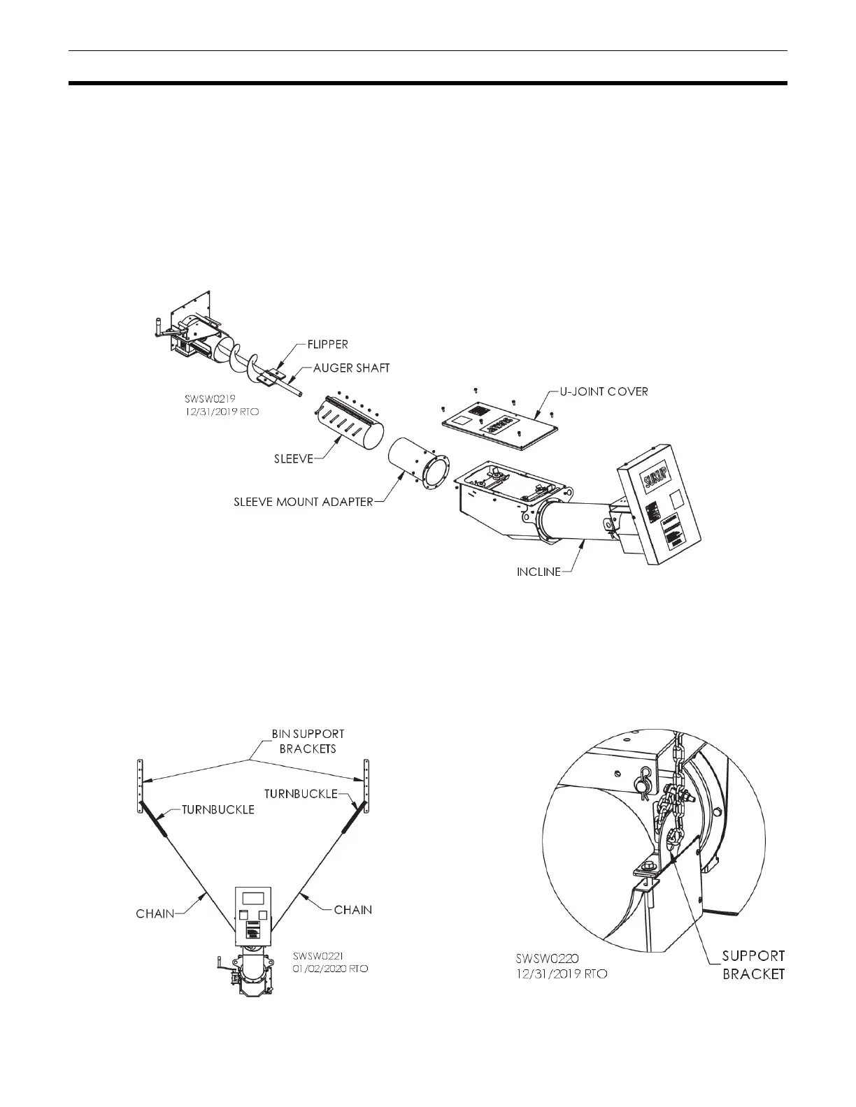
Remove flinger and auger shaft from unload auger. Save fasteners.
Remove U-joint cover from incline. See Fig. 35.
Weld 1’ section of flighting to auger. See Fig. 32.
Attach sleeve mount adapter to incline. Loosely attach connector sleeve to unload tube. Slide whole
assembly together, making sure that shaft in incline goes into unload auger. Secure with previously
removed hardware. Tighten bolts on sleeve mount.
Attach support brackets to bin, bolting them to hills of third sheet from bottom and positioned so that
incline will be centered between them. See Fig. 36.
Attach chain to each side of incline by looping through support bracket. See Fig. 37. Attach turnbuckles
to brackets and attach chains to turnbuckles. Tighten them to support incline.
Remove outer belt shield. Install pulley and belts. See Page 34 to tighten belts. Reinstall outer belt
shield.
Fig. 35 – Incline for 8” or 10” unload