SWDM240B OPERATION & MAINTENANCE MANUAL
★
Warning: Because the system parameters will be modified in this interface, improper
settings of the parameter will cause the descending using performance of the machine, even
the control less of operation resulting in heavy accidents. Thus, the "Settings" interface only
can be modified with the conduction of professional personnel of SUNWARD. Otherwise,
SUNWARD will take no responsibility for any consequence.
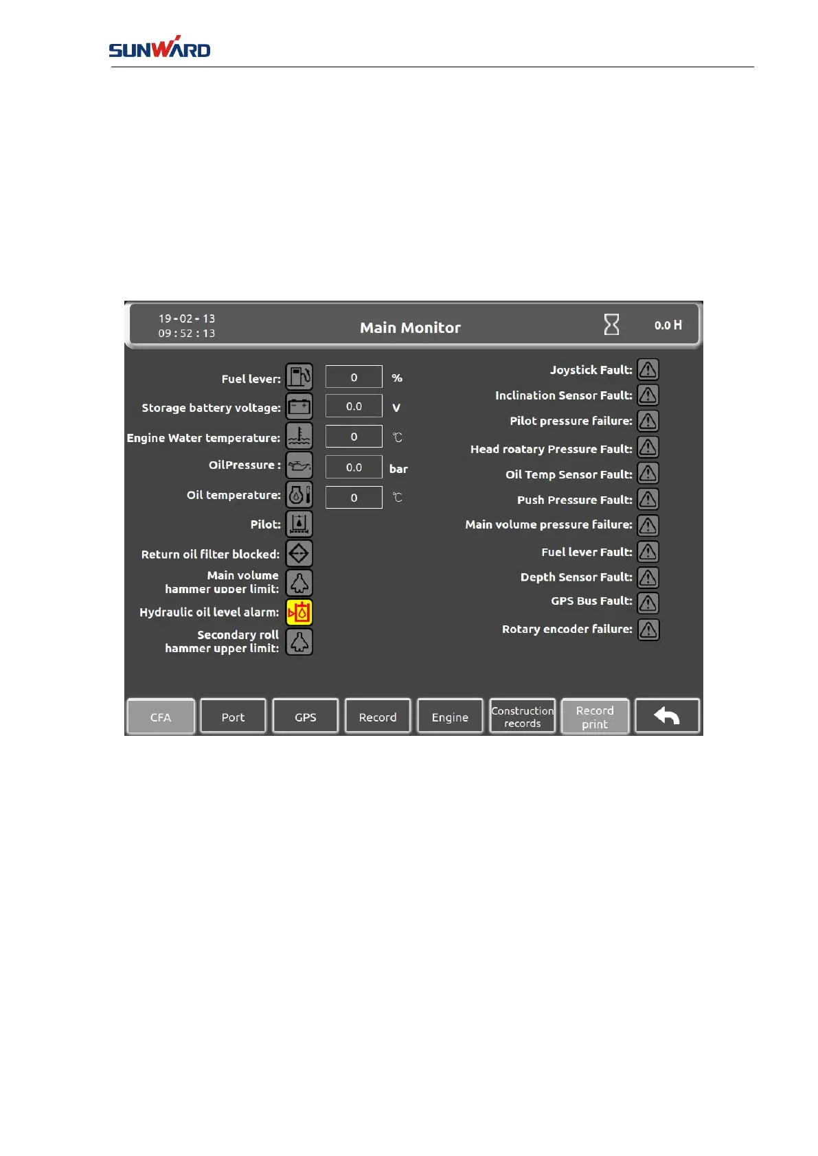
3.2.1.6 Main Monitor Interface
Click “Monitor” (key 7) in the “Main Interface” (FIG. 3.2.1-1) to enter the “Main Monitoring
Interface”.
FIG. 3.2.1-7
All the conditions of sensors and equipment alarms are displayed in this interface: when the
icon is yellow bottom with red line that indicates there is fault or alarm, you need to check the
corresponding part.
Click the "CFA" (key 1) to enter the "CFA Interface" (FIG. 3.2.1-8).
Click the "Port" (key 2) to enter the "Port Monitor Interface 1" (FIG. 3.2.1-9).
Click the "GPS" (key 3) to enter the "GPS Monitor" interface (FIG. 3.2.1-15).
Click the "Record" (key 4) to enter the "Record Interface" (FIG. 3.2.1-16).
Click the "Engine" (key 5) to enter the "Engine Fault Monitor" (FIG. 3.2.1-19).
Click the "Construction Record" (key 6) to enter the "Construction Record Interface" (FIG.
3.2.1-20).
Click the button "Record Printing"(key 7) to enter the "Record Printing Interface" (FIG.
3.2.1-21).
Click the "Return" (key 8) to enter the "Main Interface" (FIG. 3.2.1-1).