15
3.0 System Overview
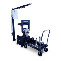
Engine Control Panel
The engine control panel has ve outputs
electrically controlled by console switches or by
programmed test proles. Four outputs provide 12V
switched DC power for ignition, starter, fuel pump,
and auxiliary control.
• Internal, automatic reset, 50A thermal breaker
on input source, automatic reset, 10-amp
polyfuse on ignition output; 14 amps on the
starter and fuel pump outputs and 5 amps on
the auxiliary output
• Emergency stop functions when used with
WinDyn limits or emergency stop switches
• Provides one unswitched, 10-amp, fused 12V
connection for external devices
• Connection for remote starter switch (not used
on SF-902S systems)
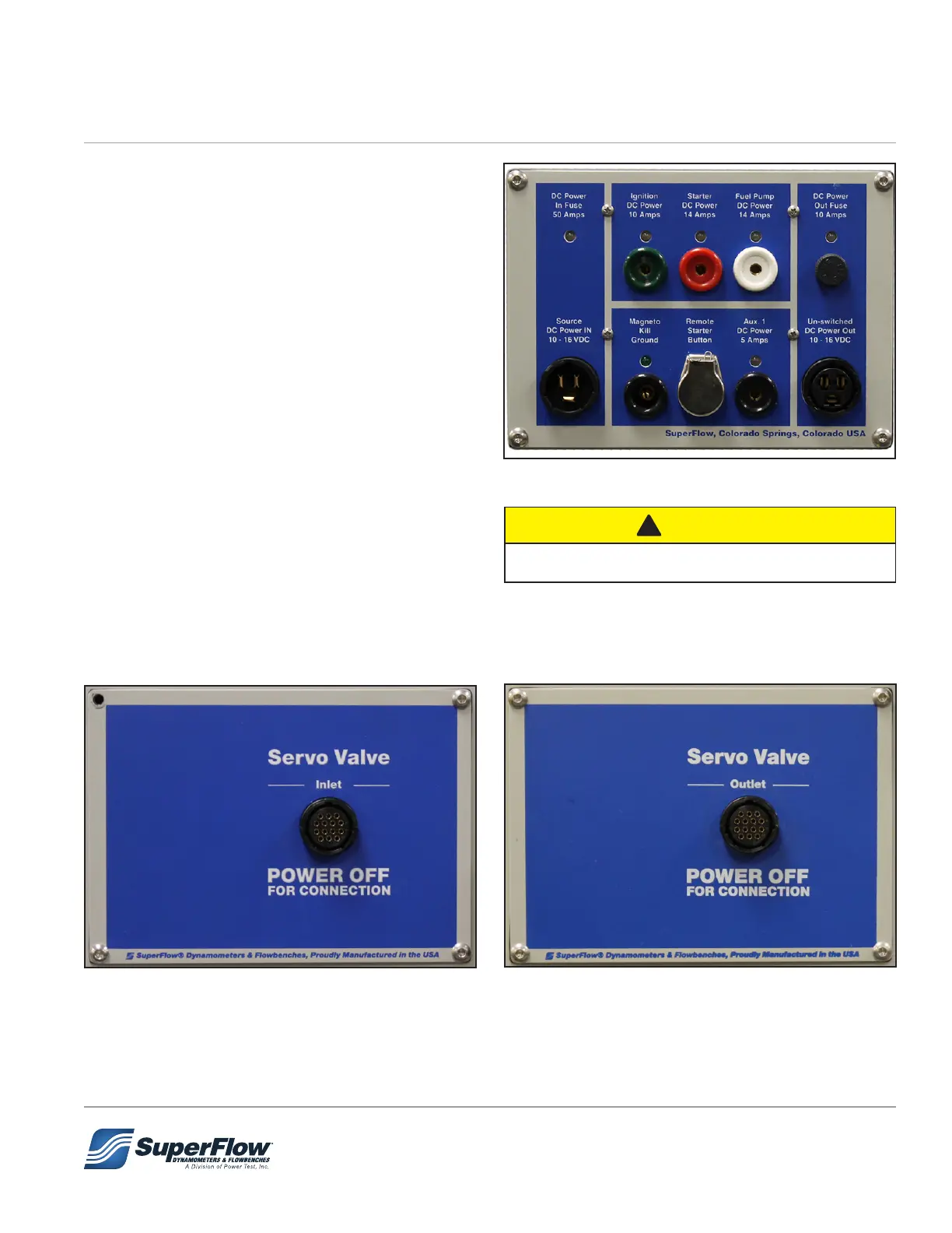
Servo Valve Panels
These panels provide connection plugs for the
servo control valve inlet and outlet cables.
Figure 3.9: Servo Valve Input Panel
Figure 3.8: Engine Control Panel
DO NOT use the Magneto Kill Ground connection.
!
CAUTION
Figure 3.10: Servo Valve Outlet Panel