26
7. Locate a small (1/4”) black nylon line on the absorber stand right-side channel with a hose tting on
the end. This is the supply line for the dyno prime, absorber seal feed, and hydraulic throttle. Attach the
hose to the supply tting on the rear left corner of the tank (Figure 4.2). The other nylon line without a
tting is the throttle drain line. It is placed so water will drain into the drain compartment.
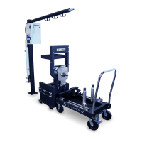
8. Install the pressure boost hose from the water inlet to the open tting on the back of the absorber
(Figure 4.3). Leave the ball valve in the closed position.
Figure 4.3 Water Supply Connections
9. Connect the water inlet and outlet ports on the rear of the tank to the appropriate sources. You may
need to slide the tank out a little to allow access to the ttings.
NOTE: Consult Power Test if information on hose sizes and pump specications is required.
• Other ttings are available on the back of the tank for auxiliary accessories such as temperature
probes, level control switches, and external coolers.
• The automatic ll valve sets the rate at which the valve shuts on and o. It should not require
adjustment. The tank level is set with the oat valve inside the tank. The tank can possibly overow the
rst time it is lled but should not happen again after the automatic valve is primed.
4.0 Installation