27
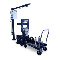
10. Install the exhaust heat shields on each side and on the rear of the stand (Figure 4.4).
Figure 4.4 Exhaust Heat Shield
11. Place the water tank cover in position on top of the tank (this cover requires periodic removal to access
inside the tank for maintenance).
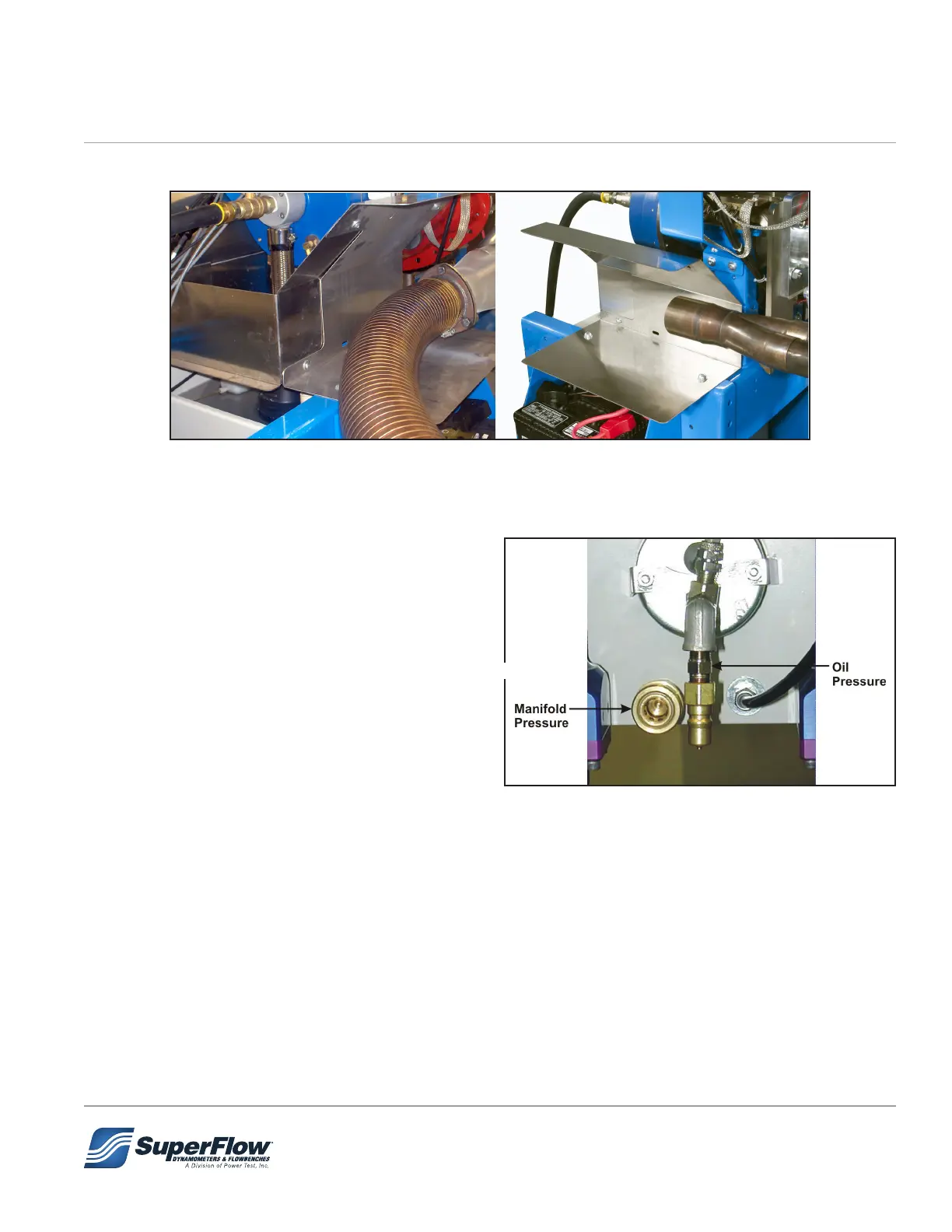
12. Install pressure hoses to the appropriate
connectors on the rear panel of the absorber
stand (Figure 5-9) using the supplied hardware.
Tee adapters are provided to connect both the
console mechanical gauges and the pressure
panel on the sensor box.
TIP: If desired, the tee adapters can be placed on
the sensor box pressure inputs.
Figure 4.5 Absorber Stand Gauge Connections
4.0 Installation