1-4
X10DRU-i+ Motherboard User’s Manual
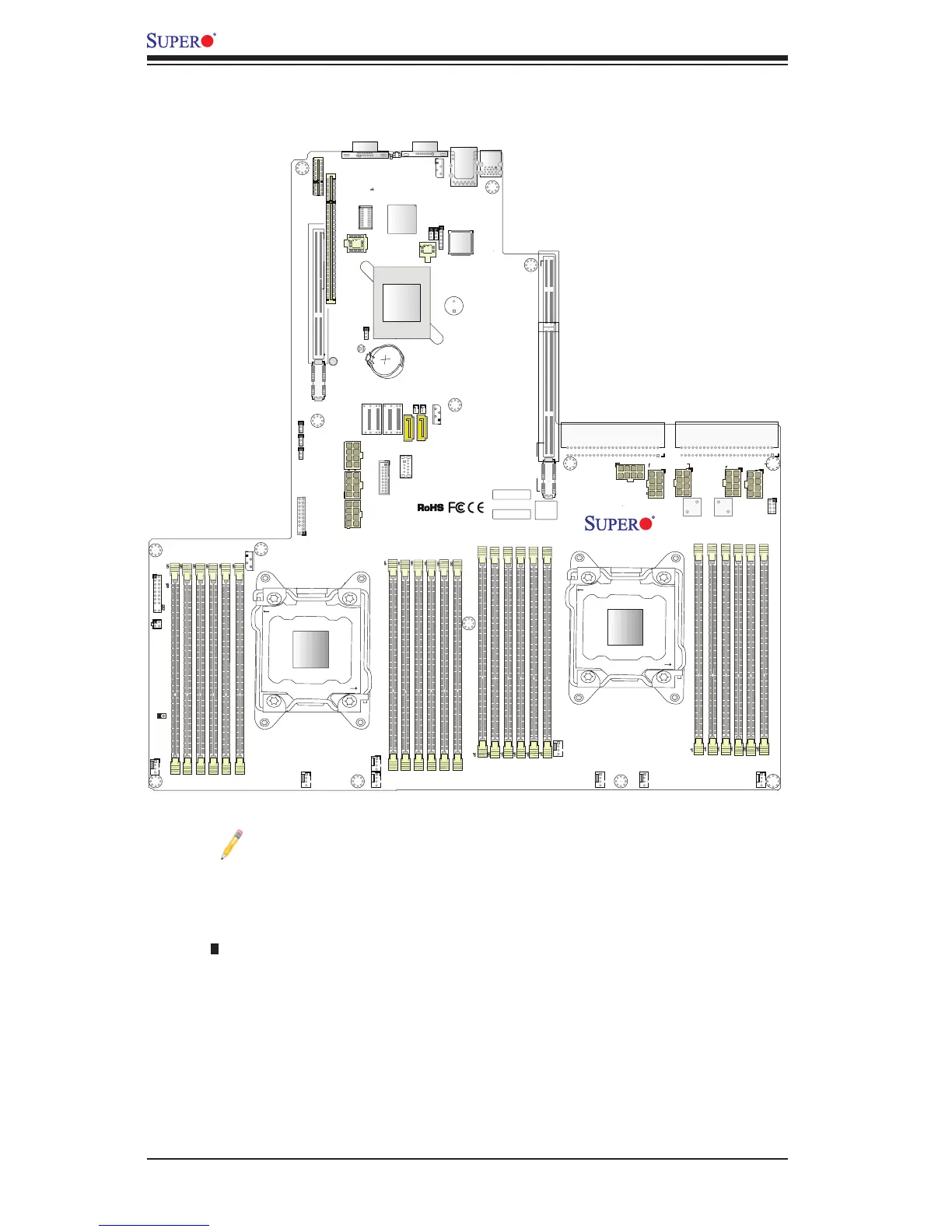
Notes:
•See Chapter 2 for detailed information on jumpers, I/O ports and JF1 front
panel connections.
•" " indicates the location of "Pin 1".
•Jumpers/LED Indicators not indicated are for internal testing only.
•Use only the correct type of onboard CMOS battery as specied by the manufac-
turer. Do not install the onboard battery upside down to avoid possible explosion.
X10DRU-i+ Quick Reference
IPMI CODE
BIOS
LICENSE
BAR CODE
JF2
L996
JTPM1
PSU2
PSU1
JUIDB2
LED1
JF1
JPME2
DAT
JWD1
JPB1
JPG1
FAN1
FAN8
FAN6
FAN7
FAN3
FAN2
I-SGPIO2
JIPMB1
LED_C1
LED_F3
LED_G1
BMC_HB_LED1
LED_B3
LED_B2
LED_B1
LED_A3
LED_A2
LED_A1
SP1
S-UM10
S-UM7
JBT1
JBAT1
PLD1
X10DRU-i+
Rev. 1.02A
USB 2 (3.0)
I-SATA5
SXB3C
SXB3B
SXB3A
SXB2
SXB1C
SXB1B
GPU PWR2
USB 3/4(3.0)
SXB1A
P2-DIMMF2
P2-DIMMF3
P2-DIMME1
P2-DIMME2
P2-DIMME3
P2-DIMMF1
P2-DIMMG1
P2-DIMMG2
P2-DIMMG3
P2-DIMMH1
P2-DIMMH2
P2-DIMMH3
CPU2
I-SATA4
CPU2_PORT1
CPU1
P1-DIMMC1
P1-DIMMC2
P1-DIMMC3
P1-DIMMD1
P1-DIMMD3
P1-DIMMD2
CPU1_PORT2C
CPU1_PORT2A
CPU1_PORT3A
CPU1_PORT1
S-SATA0~3

 Loading...


