Power Fail LED
HDD LED
FP PWRLED
Reset
PWR
3.3 V
UID Switch
UID LED
Ground
Ground
1920
3.3V
X
Ground
NMI
X
NIC2 Link LED
NIC2 Activity LED
NIC1 Activity LED
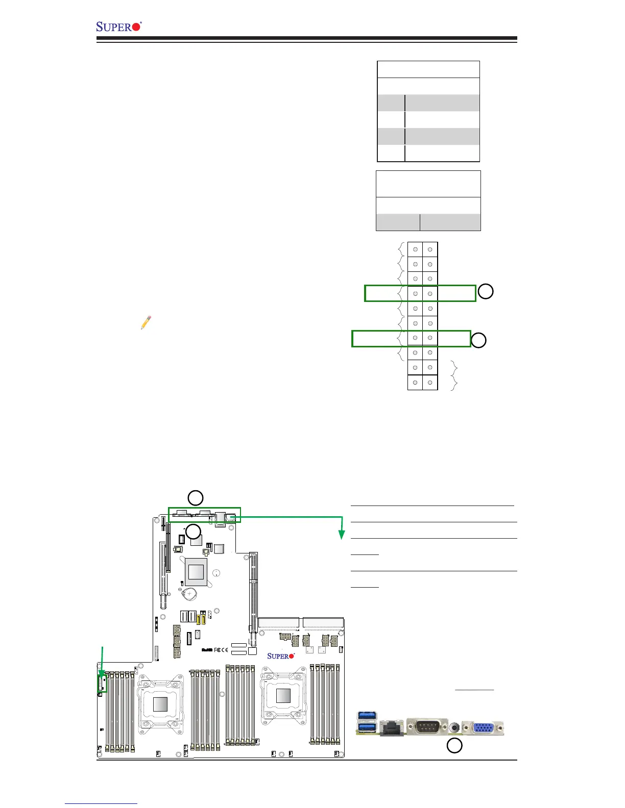
1. UID Button (on the I/O Back Panel)
2. Rear UID LED (on the motherboard)
3. Front UID LED (on the Front CTRL
Panel)
4. Front UID Switch (on the Front CTRL
Panel)
Unit Identier Buttons/UID LED Indicators
A rear unit identier button (JUIDB2) is located
next to the COM port on the IO back panel,
and a front UID button is located on pin 13 on
the front control panel (JF1). The rear UID LED
(LED1) is located next to the rear UID button,
and the front UID LED is located on pins 7
on JF1. When you press the rear UID button,
both front and rear UID LED indicators will be
turned on. Press the UID button again to turn
off the LEDs. The UID Indicators provide easy
identication of a system unit that may be in
need of service. Refer to the layout below for
the locations of the front control panel and the
I/O back panel.
Note: UID can also be triggered via
IPMI on the motherboard. For more
information on IPMI, please refer to
the IPMI User's Guide posted on our
website @http://www.supermicro.
com.
UID Button
Pin# Denition
1 Ground
2 Ground
3 Button In
4 Button In
UID LED
Status
Color/State Status
Blue: On Unit Identied

 Loading...


