Chapter 2: Installation
2-17
IPMI CODE
BIOS
LICENSE
BAR CODE
JF2
L996
JTPM1
PSU2
PSU1
JUIDB2
LED1
JF1
JPME2
DAT
JWD1
JPB1
JPG1
FAN1
FAN8
FAN6
FAN7
FAN3
FAN2
I-SGPIO2
JIPMB1
LED_C1
LED_F3
LED_G1
BMC_HB_LED1
LED_B3
LED_B2
LED_B1
LED_A3
LED_A2
LED_A1
SP1
S-UM10
S-UM7
JBT1
JBAT1
PLD1
X10DRU-i+
Rev. 1.02A
USB 2 (3.0)
I-SATA5
SXB3C
SXB3B
SXB3A
SXB2
SXB1C
SXB1B
GPU PWR2
USB 3/4(3.0)
SXB1A
P2-DIMMF2
P2-DIMMF3
P2-DIMME1
P2-DIMME2
P2-DIMME3
P2-DIMMF1
P2-DIMMG1
P2-DIMMG2
P2-DIMMG3
P2-DIMMH1
P2-DIMMH2
P2-DIMMH3
CPU2
I-SATA4
CPU2_PORT1
CPU1
P1-DIMMC1
P1-DIMMC2
P1-DIMMC3
P1-DIMMD1
P1-DIMMD3
P1-DIMMD2
CPU1_PORT2C
CPU1_PORT2A
CPU1_PORT3A
CPU1_PORT1
S-SATA0~3
COM1
P1-DIMMA1
P1-DIMMA2
P1-DIMMA3
P1-DIMMB1
P1-DIMMB2
P1-DIMMB3
BP PWR2
GPU PWR1
VGA
IPMI_LAN
UID
USB 0/1(3.0)
BP PWR1
JSD1
LED_C2
LED_C3
LED_D1
LED_D2
LED_D3
FAN5
LED_G2
LED_G3
LED_H1
LED_H2
LED_H3
LED_F2
LED_F1
LED_E3
LED_E2
LED_E1
LED2
CPU2_PORT0
HDD_LED1
GPU PWR3
GPU PWR4
L995
CLOSE 1st
OPEN 1st
CLOSE 1st
OPEN 1st
PCH
BMC
BIOS
CPU2_PORT3A
CLK
JL1
FAN4
JPW21
JPW19
JPW22
JPW23
JGPW1
CPU2_PORT2C
CPU2_PORT3C
CPU2_PORT2A
TPM/Port80
I-SATA0~3
JSD2
JNVI2C1
JNVI2C2
CPU1_PORT3C
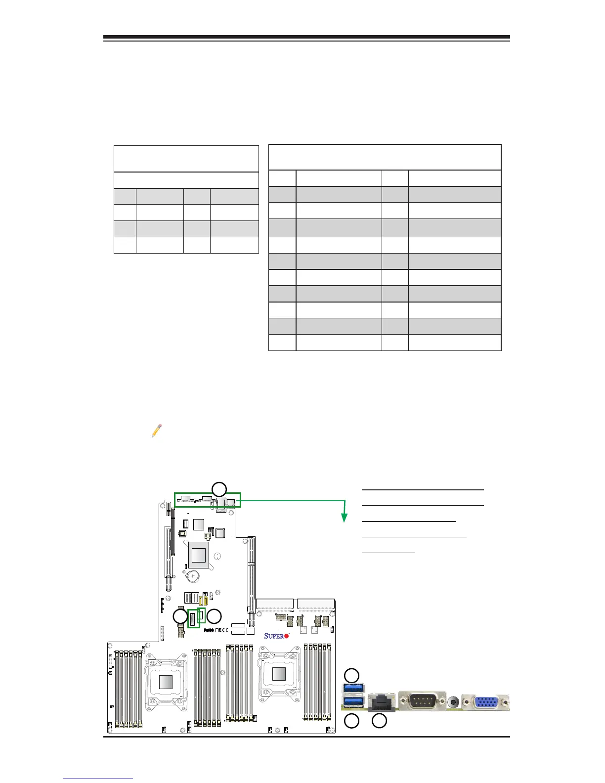
1. Backpanel USB0 (USB3.0)
2. Backpanel USB1 (USB3.0)
3. FP USB 2 (USB3.0)
4. FP USB 3/4 (USB 3.0)
5. IPMI_LAN
Universal Serial Bus (USB)
Two USB 3.0 ports (USB 0/1), located on the I/O back panel, provide rear chassis
USB support. A Type A USB connector (USB 2), and a USB header with two USB
connections (USB 3/4) provide total of three USB 3.0 connections for front access.
(Cables are not included). See the tables below for pin denitions.
Back Panel USB (3.0) 0/1, 2
Pin Denitions
Pin# Denition Pin# Denition
1 +5V 5 +5V
2 USB_PN1 6 USB_PN0
3 USB_PP1 7 USB_PP0
4 Ground 8 Ground
USB (3.0) USB 3/4
Pin Denitions
Pin# Description Pin# Description
1 USB3.0_Front_VCC
2 USB3_RE_RXN6 19 USB3.0_Front_VCC
3 USB3_RE_RXP6 18 USB3_RE_RXN5
4 Ground 17 USB3_RE_RXP5
5 USB3_RE_TXN6 16 Ground
6 USB3_RE_TXP6 15 USB3_RE_TXN5
7 Ground 14 USB3_RE_TXP5
8 USB2_N8 13 Ground
9 USB2_P8 12 USB2_N9
10 Ground 11 USB2_P9
IPMI_LAN Port
An IPMI_ LAN port is located on the I/O back panel on the motherboard. This port
accepts the RJ45 type cable. Please refer to the LED Indicator Section for LAN
LED information.
Note: Also, for additional LAN connections, please install an appropriate
Ultra riser card on Slot SXB3A/3B/3C. Please refer to the AOC list posted
at http://www.supermicro.com/support/resources/aoc/aoc_compatibility_ul-
tra.cfm for more info.

 Loading...


