Chapter 2: Installation
2-21
Power Button
OH/Fan Fail/
PWR Fail LED)
1
NIC1 Link LED
Reset Button
2
Power Fail LED
HDD LED
FP PWRLED
Reset
PWR
3.3 V
UID Switch
UID LED
Ground
Ground
1920
3.3V
X
Ground
NMI
X
NIC2 Link LED
NIC2 Activity LED
NIC1 Activity LED
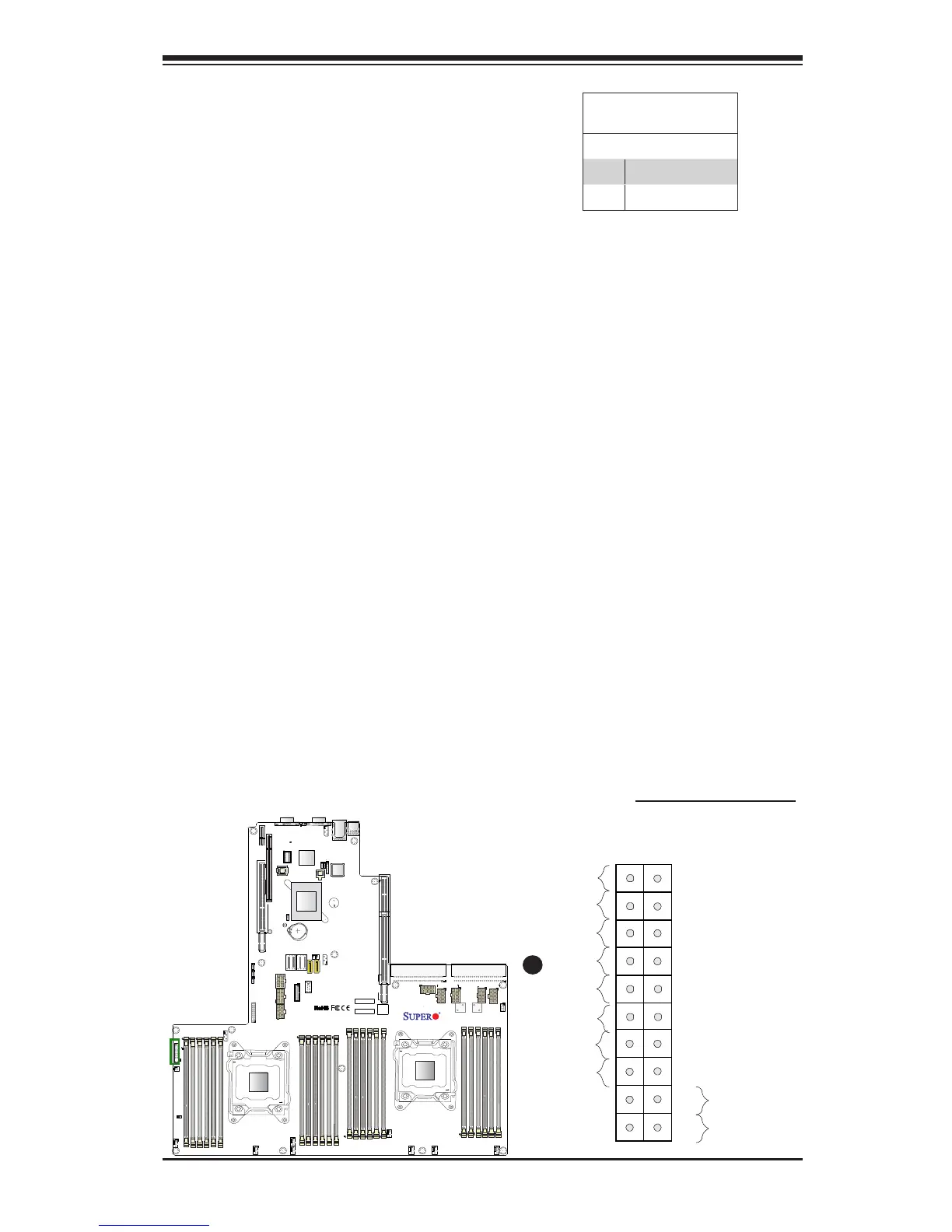
HDD LED/UID Switch
The HDD LED/UID switch connection
is located on pins 13 and 14 of JF1.
Attach a cable to pin 14 to show HDD
activity status. Attach a cable to pin 13
to use UID button. See the table on
the right for pin denitions.
HDD LED/UID Switch
Pin Denitions (JF1)
Pin# Denition
13 UID Switch
14 HD Active
A. HDD LED/UID Switch
A

 Loading...


