Power Button
OH/Fan Fail/
PWR Fail LED)
1
NIC1 Link LED
Reset Button
2
Power Fail LED
HDD LED
FP PWRLED
Reset
PWR
3.3 V
UID Switch
UID LED
Ground
Ground
1920
3.3V
X
Ground
NMI
X
NIC2 Link LED
NIC2 Activity LED
NIC1 Activity LED
Power Fail LED
The Power Fail LED connection is
located on pins 5 and 6 of JF1. Re-
fer to the table on the right for pin
denitions.
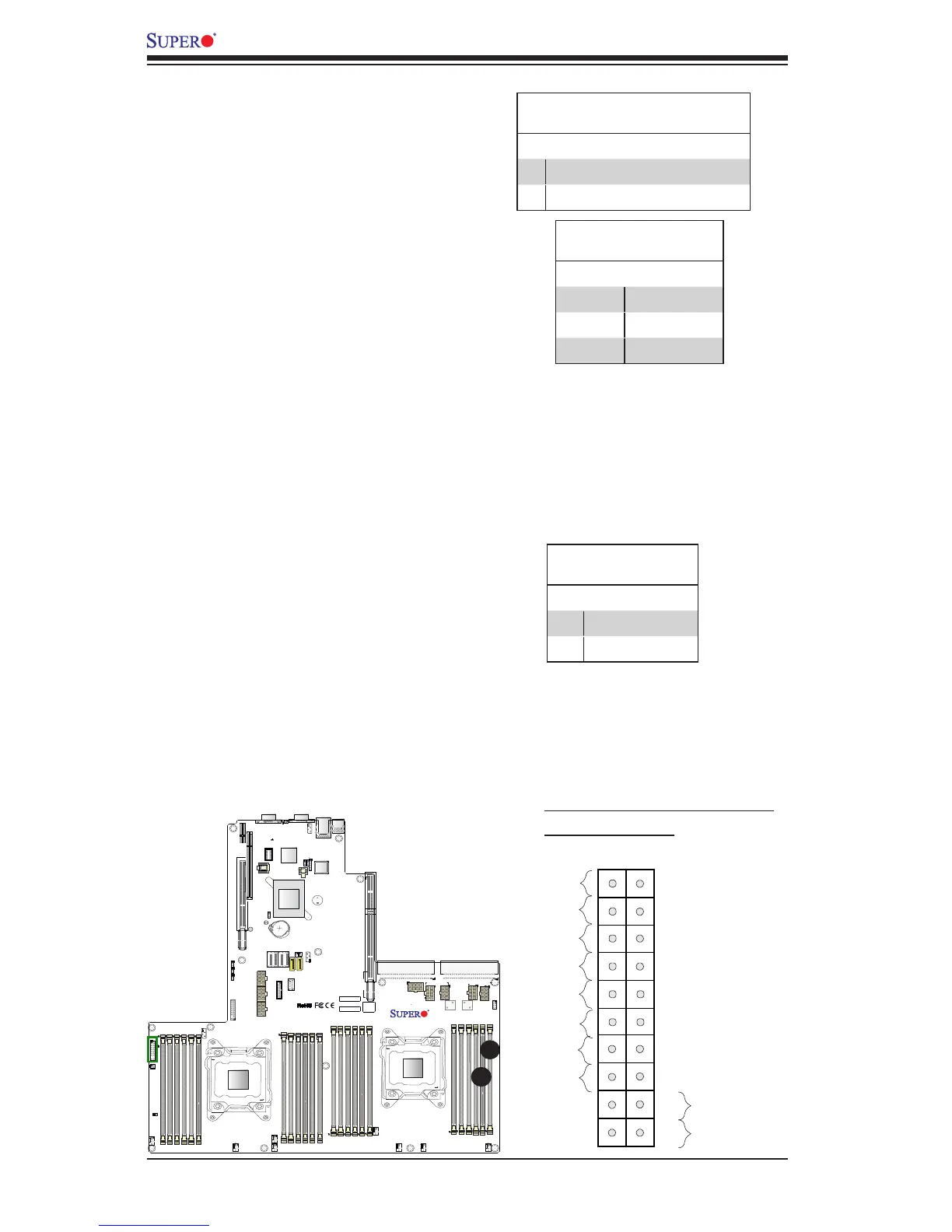
A. OH/Fail/PWR Fail LED/UID LED
B. PWR Supply Fail
PWR Fail LED
Pin Denitions (JF1)
Pin# Denition
5 3.3V
6 PWR Supply Fail
B
A
Overheat (OH)/Fan Fail/PWR Fail/
UID LED
Connect an LED cable to pins 7 and
8 of JF1 to use the Overheat/Fan Fail/
Power Fail and UID LED connections.
The red LED on pin 8 provides warn-
ings of overheat, fan failure or power
failure. The blue LED on pin 7 works
as the front panel UID LED indicator.
Refer to the table on the right for pin
denitions.
OH/Fan Fail/ PWR Fail/Blue_UID
LED Pin Denitions (JF1)
Pin# Denition
7 Blue_UID LED
8 OH/Fan Fail/Power Fail
OH/Fan Fail/PWR Fail
LED Status (Red LED)
State Denition
Off Normal
On Overheat
Flashing Fan Fail

 Loading...


