EasyManuals Logo

Supermicro SUPERO X10DRU-i+ User Manual

Supermicro SUPERO X10DRU-i+
115 pages
To Next Page IconTo Next Page
To Previous Page IconTo Previous Page
Page #46 background imageLoading...
Page #46 background image
2-24
X10DRU-i+ Motherboard User’s Manual
IPMI CODE
BIOS
LICENSE
BAR CODE
JF2
L996
JTPM1
PSU2
PSU1
JUIDB2
LED1
JF1
JPME2
DAT
JWD1
JPB1
JPG1
FAN1
FAN8
FAN6
FAN7
FAN3
FAN2
I-SGPIO2
JIPMB1
LED_C1
LED_F3
LED_G1
BMC_HB_LED1
LED_B3
LED_B2
LED_B1
LED_A3
LED_A2
LED_A1
SP1
S-UM10
S-UM7
JBT1
JBAT1
PLD1
X10DRU-i+
Rev. 1.02A
USB 2 (3.0)
I-SATA5
SXB3C
SXB3B
SXB3A
SXB2
SXB1C
SXB1B
GPU PWR2
USB 3/4(3.0)
SXB1A
P2-DIMMF2
P2-DIMMF3
P2-DIMME1
P2-DIMME2
P2-DIMME3
P2-DIMMF1
P2-DIMMG1
P2-DIMMG2
P2-DIMMG3
P2-DIMMH1
P2-DIMMH2
P2-DIMMH3
CPU2
I-SATA4
CPU2_PORT1
CPU1
P1-DIMMC1
P1-DIMMC2
P1-DIMMC3
P1-DIMMD1
P1-DIMMD3
P1-DIMMD2
CPU1_PORT2C
CPU1_PORT2A
CPU1_PORT3A
CPU1_PORT1
S-SATA0~3
COM1
P1-DIMMA1
P1-DIMMA2
P1-DIMMA3
P1-DIMMB1
P1-DIMMB2
P1-DIMMB3
BP PWR2
GPU PWR1
VGA
IPMI_LAN
UID
USB 0/1(3.0)
BP PWR1
JSD1
LED_C2
LED_C3
LED_D1
LED_D2
LED_D3
FAN5
LED_G2
LED_G3
LED_H1
LED_H2
LED_H3
LED_F2
LED_F1
LED_E3
LED_E2
LED_E1
LED2
CPU2_PORT0
HDD_LED1
GPU PWR3
GPU PWR4
L995
CLOSE 1st
OPEN 1st
CLOSE 1st
OPEN 1st
PCH
BMC
BIOS
CPU2_PORT3A
CLK
JL1
FAN4
JPW21
JPW19
JPW22
JPW23
JGPW1
CPU2_PORT2C
CPU2_PORT3C
CPU2_PORT2A
TPM/Port80
I-SATA0~3
JSD2
JNVI2C1
JNVI2C2
CPU1_PORT3C
2-7 Connecting Cables
Power Connectors
The X10DRU-i+ motherboard supports the following power congurations:
• Two (2) SMCI-proprietary main power supply units (PSU1: for CPU1 platform
support, PSU2: for CPU2 platform support)
• Two (2) backplane power-connector units (each unit comprised of two 8-pin
power connectors) for backplane device use (BP PWR1: CPU1 platform support,
BP PWR2: for CPU2 platform support)
• Four (4) 8-pin power-connectors (GPU PWR1-4) used for GPU devices
• One (1) 4-pin power connector (JF2) used for HDD devices
Warning! To provide adequate power to your system and to avoid damaging the power
supply or the motherboard, be sure to connect all power connectors mentioned above
to the power supply. Failure in doing so may void the manufacturer warranty on your
power supply and motherboard.
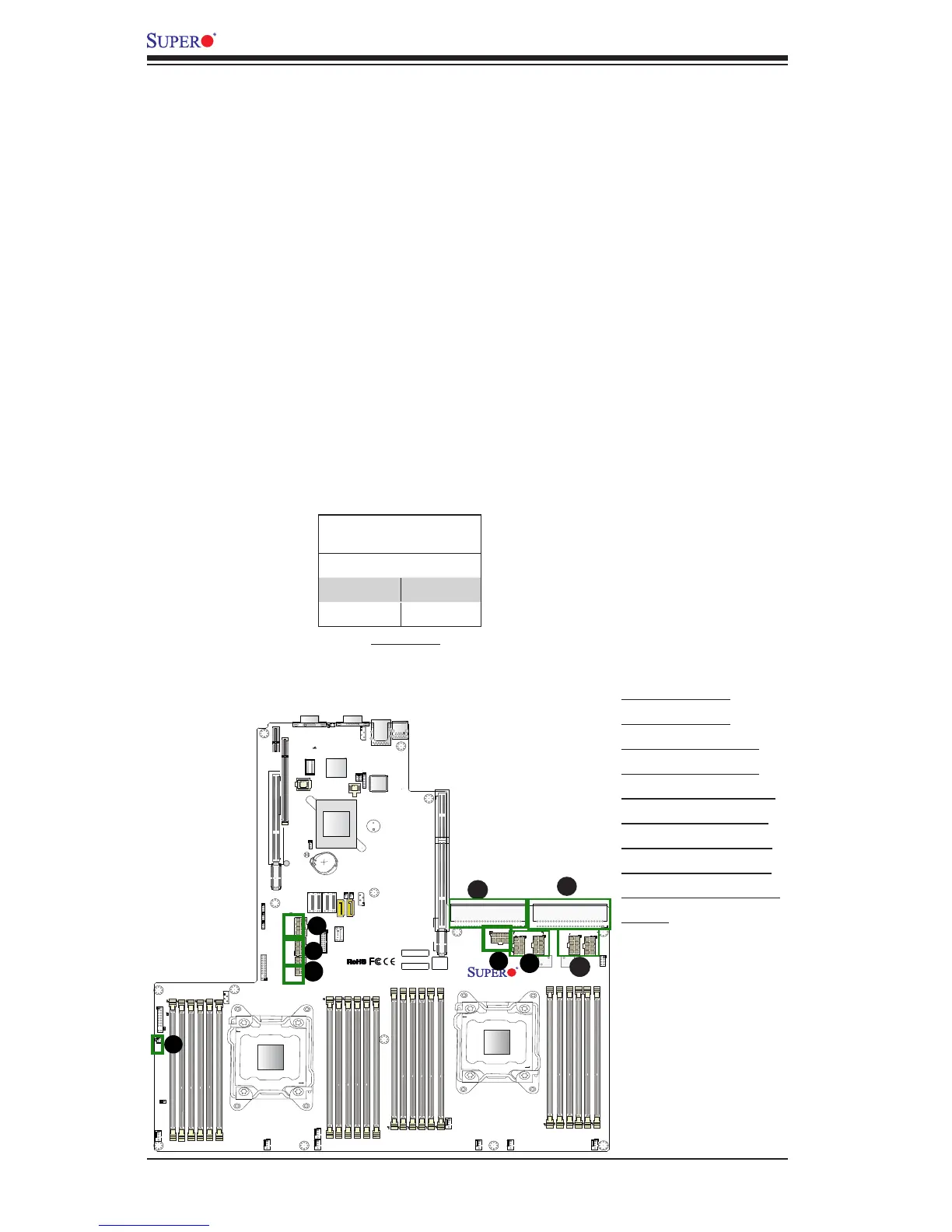
A. PSU1 (Req'd)
B. PSU2 (Req'd)
C. BP PWR1 (Req'd)
D. BP PWR2 (Req'd)
E. GPU PWR1 (Req'd)
F. GPU PWR2 (Req'd)
G. GPU PWR3 (Req'd)
H. GPU PWR4 (Req'd)
I. JF2: 4-pin HDD PWR
(Req'd)
A
B
C
(Required)
8-pin GPU PWR
Pin Denitions
Pins Denition
1 through 4 Ground
5 through 8 +12V
D
E
F
H
G
I

Table of Contents

Questions and Answers:

Question and Answer IconNeed help?

Do you have a question about the Supermicro SUPERO X10DRU-i+ and is the answer not in the manual?

Supermicro SUPERO X10DRU-i+ Specifications

General IconGeneral
BrandSupermicro
ModelSUPERO X10DRU-i+
CategoryMotherboard
LanguageEnglish

Related product manuals