47
Chapter 2: Maintenance and Component Installation
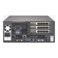
Power Supply
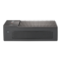
The E403-9P-FN2T includes an internal power supply that can be replaced.
Removing and Replacing the Power Supply
1. Remove the power cord by following the steps in Section 2.1, and remove the top cover.
2. To access the motherboard, remove the expansion card module and the hard drives
as described previously. Make sure to disconnect the extension cables from the
motherboard and the power supply.
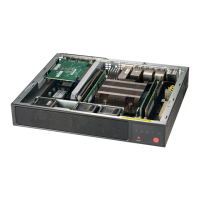
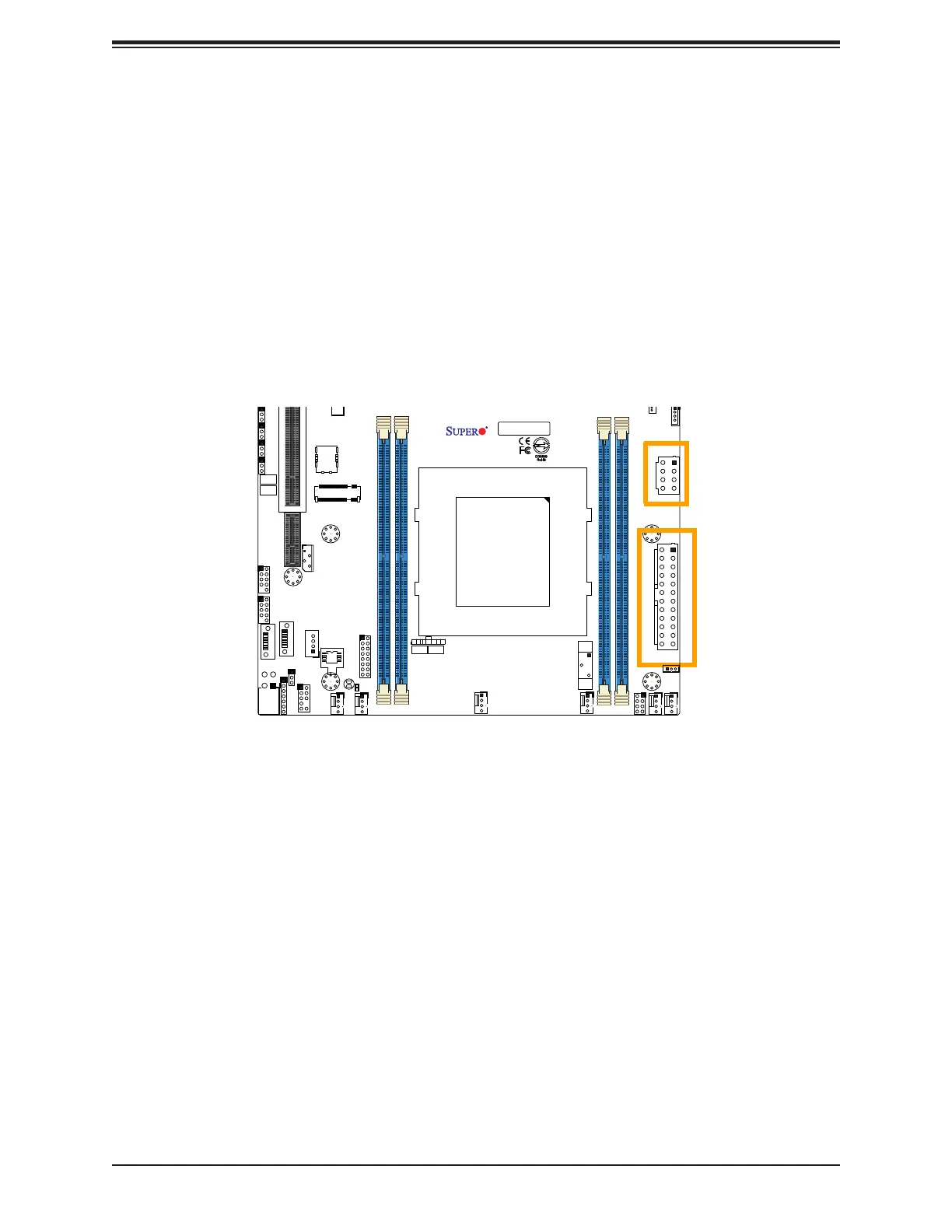
3. With access to the motherboard, remove the ATX power connection (JPWR1) and the
8-pin power connection (JPV1).
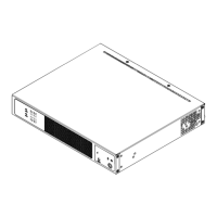
4. Remove three screws on the chassis as shown in Figure 2-17 and set them aside.
5. Lift the power supply out of the chassis.
6. Place a new power supply into the chassis with the fan at the top rear. Install the three
screws.
7. Reconnect the ATX and 8-pin power connection to the motherboard.
8. If necessary reconnect the expansion card power supply and replace the expansion card
module.
9. Reconnect the hard drive data and power extension cables and replace the hard drive
cage.
10. Replace the chassis top cover.
11. Reconnect the power supply cord to the power supply inlet and the power source.
FAN4
FAN3
FAN1
FAN2
FANB
FANA
JD1
JF1
JNVI2C1
JBT1
JTPM1
JPWR1
S-SGPIO1
JSTBY1
JPG1
J1
JSMB1
JI2C1 JI2C2 JWD1
JPME2
JVRM1
JPL2 JPL3
JPT1
MH1
MH7
MH2
MH4
MH5
BT1
JMD2_SRW1
LED1
S-SATA2
S-SATA3
JSIM1
JPV1
JRK1
JPW1
JMD1: M.2-H
JSDP3
JSDP2
JSDP1
LEDT1
PRESS FIT
AC
CA CA
A
C
A
C
CA CA
DESIGNED IN USA
BAR CODE
X11SDW-4C-TP13F
REV:1.01
USB 2/3
USB 0/1
2-3:DISABLE
1-2:ENABLE
JPT1:TPM
JSXB1C
CPU
JPL3:
LAN 6/7/8/9
1-2:ENABLE
2-3:DISABLE
JPL2:
2-3:DISABLE
1-2:ENABLE
LAN 2/3/4/5
PCI-E 3.0 X2 / S-SATA4
JMD2:M.2-H
PCI-E 3.0 X4 / I-SATA4
UID
LAN 2/3/4/5/6/7/8/9
LAN 12/13
LAN 10/11
IPMI_LAN
ON
PWR
RST
X
NIC2
FF
OH
LED
NIC1
HDD
LED
PWR
JF1:
4-7:SPEAKER
1-3:PWR LED
JD1:
DIMMA1
DIMMB1
DIMME1
DIMMD1
JPH1
Figure 2-16. Removing the ATX and 8-pin Connections