Chapter 1: Introduction
1-3
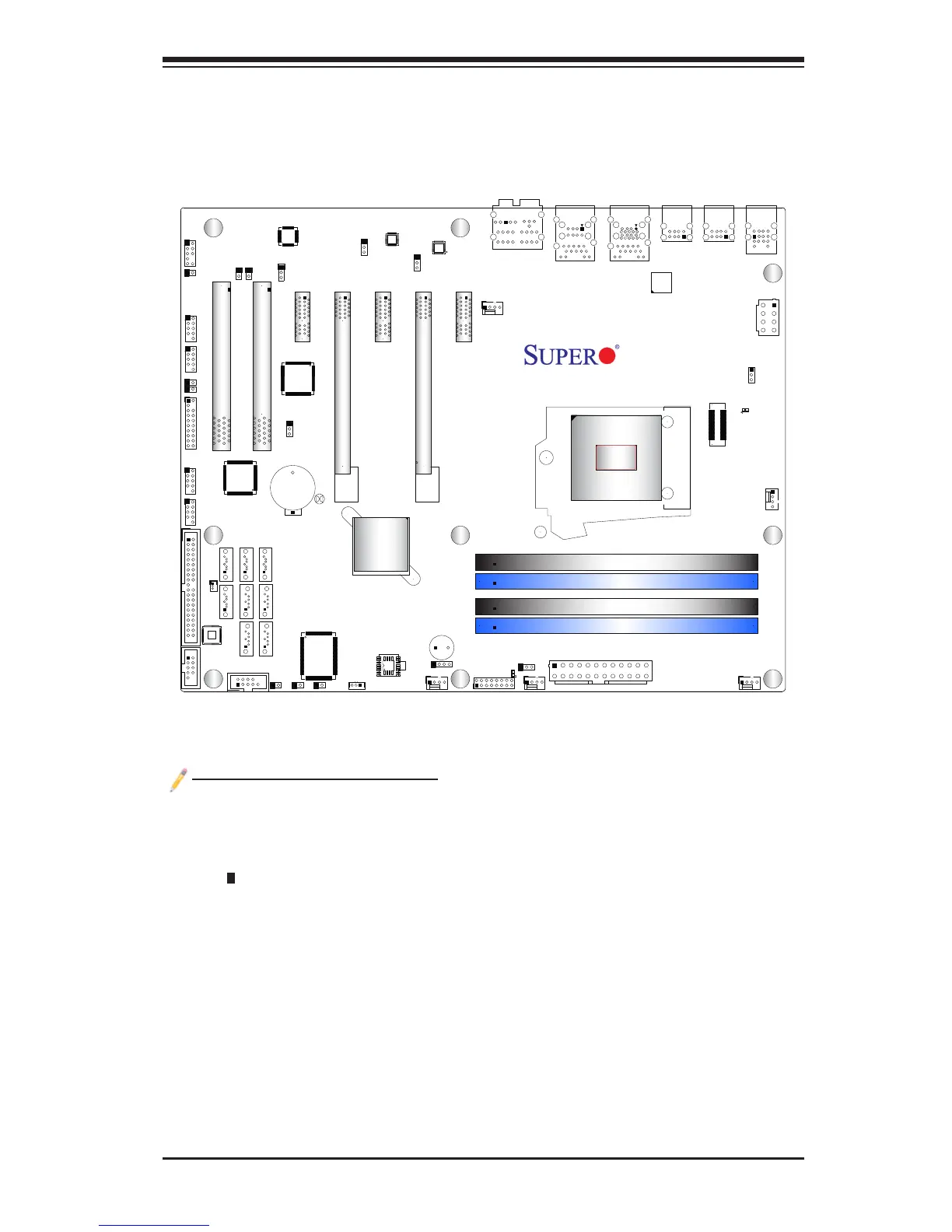
C7P67 Motherboard Layout
Important Notes to the User
See Chapter 2 for detailed information on jumpers, I/O ports and JF1 front •
panel connections.
" " indicates the location of "Pin 1".
•
Jumpers not indicated are for testing only. •
When LED1 (Onboard Power LED Indicator) is on, system power is on. Unplug •
the power cable before installing or removing any components.
CPU Overclocking is supported by this motherboard; however, SMCI does not
•
recommend CPU Overclocking and cannot resume any responsibility or liability
of out_of_spec. overclocking.
CATERR_LED is for internal testing only.
•
JTPM1
M-SATA1
M-SATA0
I-SATA1
I-SATA0
LED1
JWOL
JF1
JPW1
JBT1
I-SATA5 I-SATA2
I-SATA4
I-SATA3
B1
SP1
JD1
JWF1
J15
1
JPME1
JHD_AC1
JSPDIF_IN
JSPDIF_OUT
JI2C1
JI2C2
JWOR
JL1
CATERR_LED1
JPW2
FANA
FAN4
FAN2
FAN1
FAN3
JPL1
JPAC1
JPI1
JPL2
JLED
1
JCPUVRD_SMB
SATA 3.0
USB3.0 0/1
IDE
1394_1
1394_2
Slot1 PCI 33MHZ
Slot2 PCI 33MHZ
Slot3 PCI-E 2.0 X1
Slot4 PCI-E 2.0 X8 (INX16)
Slot5 PCI-E 2.0 X1
Slot6 PCI-E 2.0 X16
Slot7 PCI-E 2.0 X1
USB11/12
USB13/10
USB8/9
AUDIO FP
USB2/3
USB4/5
Buzzer
COM2
COM1
HD AUDIO
LAN2
USB 2.0 0/1
Always Populate Blue Sockets First
Unbuf. Non-ECC DDR3 DIMM Required
LAN1
CPU
JITP1
DIMM2A
DIMM2B
DIMM1B
DIMM1A
KB/Mouse
Rev. 1.01
C7P67
J18
LAN CTRL
LAN CTRL
Audio CTRL
Battery
BIOS
USB 3.0 CTRL
Intel
P67 PCH
LGA1155
Marvel
SATA 3 CTRL
S I/O
1394
CTRL
PCI
CTRL
FP CTRL