Chapter 2: Installation
2-29
JTPM1
M-SATA1
M-SATA0
I-SATA1
I-SATA0
LED1
JWOL
JF1
JPW1
JBT1
I-SATA5 I-SATA2
I-SATA4
I-SATA3
B1
SP1
JD1
JWF1
J15
1
JPME1
JHD_AC1
JSPDIF_IN
JSPDIF_OUT
JI2C1
JI2C2
JWOR
JL1
CATERR_LED1
JPW2
FANA
FAN4
FAN2
FAN1
FAN3
JPL1
JPAC1
JPI1
JPL2
JLED
1
JCPUVRD_SMB
SATA 3.0
USB3.0 0/1
IDE
1394_1
1394_2
Slot1 PCI 33MHZ
Slot2 PCI 33MHZ
Slot3 PCI-E 2.0 X1
Slot4 PCI-E 2.0 X8 (INX16)
Slot5 PCI-E 2.0 X1
Slot6 PCI-E 2.0 X16
Slot7 PCI-E 2.0 X1
USB11/12
USB13/10
USB8/9
AUDIO FP
USB2/3
USB4/5
Buzzer
COM2
COM1
HD AUDIO
LAN2
USB 2.0 0/1
Always Populate Blue Sockets First
Unbuf. Non-ECC DDR3 DIMM Required
LAN1
CPU
JITP1
DIMM2A
DIMM2B
DIMM1B
DIMM1A
KB/Mouse
Rev. 1.01
C7P67
J18
LAN CTRL
LAN CTRL
Audio CTRL
Battery
BIOS
USB 3.0 CTRL
Intel
P67 PCH
LGA1155
Marvel
SATA 3 CTRL
S I/O
1394
CTRL
PCI
CTRL
FP CTRL
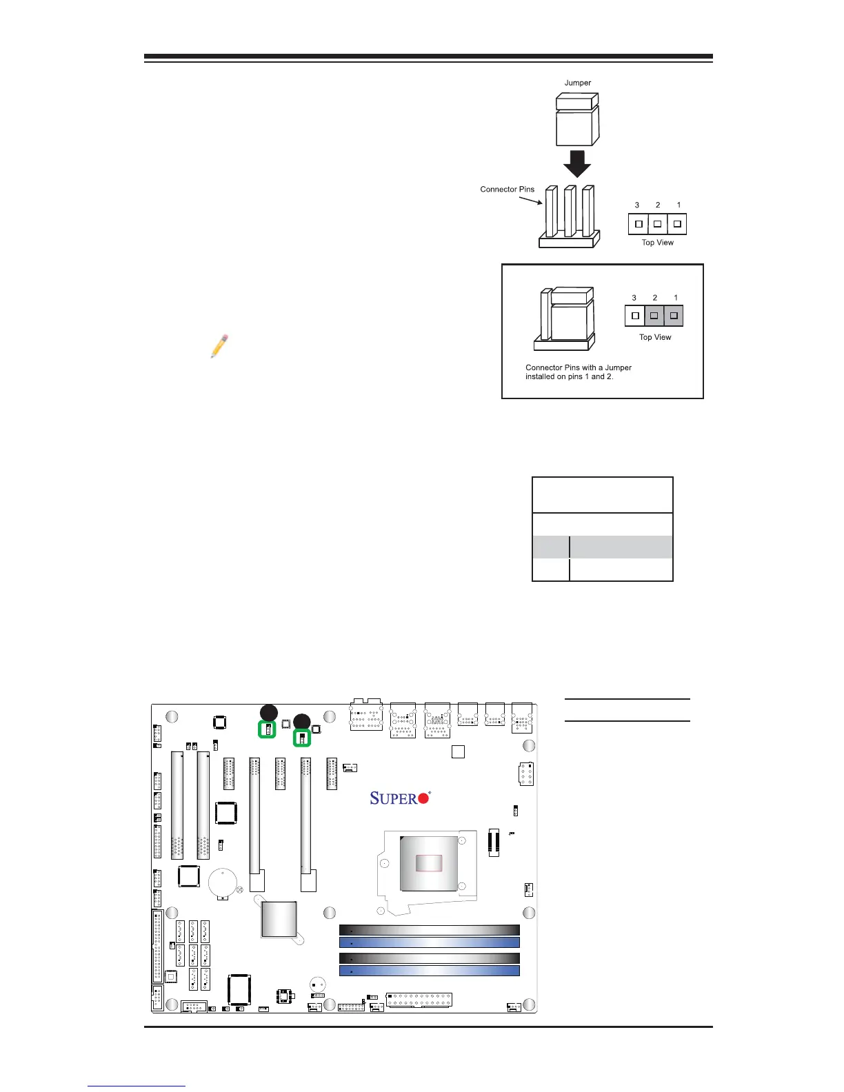
2-7 Jumper Settings
Explanation of Jumpers
To modify the operation of the mother-
board, jumpers can be used to choose
between optional settings. Jumpers create
shorts between two pins to change the
function of the connector. Pin 1 is identifi ed
with a square solder pad on the printed
circuit board.
Note: On two pin jumpers,
"Closed" means the jumper is on,
and "Open" means the jumper is
off the pins.
A. LAN Port 1 Enable
B. LAN Port 2 Enable
LAN Port Enable/Disable
Jumpers JPL1/JPL2 enable or disable
LAN Port 1/LAN Port 2 on the moth-
erboard. See the table on the right for
jumper settings. The default setting is
enabled.
GLAN Enable
Jumper Settings
Pin# Defi nition
1-2 Enabled (default)
2-3 Disabled
A
B