2-22
C7P67 User's Manual
JTPM1
M-SATA1
M-SATA0
I-SATA1
I-SATA0
LED1
JWOL
JF1
JPW1
JBT1
I-SATA5 I-SATA2
I-SATA4
I-SATA3
B1
SP1
JD1
JWF1
J15
1
JPME1
JHD_AC1
JSPDIF_IN
JSPDIF_OUT
JI2C1
JI2C2
JWOR
JL1
CATERR_LED1
JPW2
FANA
FAN4
FAN2
FAN1
FAN3
JPL1
JPAC1
JPI1
JPL2
JLED
1
JCPUVRD_SMB
SATA 3.0
USB3.0 0/1
IDE
1394_1
1394_2
Slot1 PCI 33MHZ
Slot2 PCI 33MHZ
Slot3 PCI-E 2.0 X1
Slot4 PCI-E 2.0 X8 (INX16)
Slot5 PCI-E 2.0 X1
Slot6 PCI-E 2.0 X16
Slot7 PCI-E 2.0 X1
USB11/12
USB13/10
USB8/9
AUDIO FP
USB2/3
USB4/5
Buzzer
COM2
COM1
HD AUDIO
LAN2
USB 2.0 0/1
Always Populate Blue Sockets First
Unbuf. Non-ECC DDR3 DIMM Required
LAN1
CPU
JITP1
DIMM2A
DIMM2B
DIMM1B
DIMM1A
KB/Mouse
Rev. 1.01
C7P67
J18
LAN CTRL
LAN CTRL
Audio CTRL
Battery
BIOS
USB 3.0 CTRL
Intel
P67 PCH
LGA1155
Marvel
SATA 3 CTRL
S I/O
1394
CTRL
PCI
CTRL
FP CTRL
2-6 Connecting Cables
This section provides brief descriptions and pin-out defi nitions for onboard headers
and connectors. Be sure to use the correct cable for each header or connector. For
information on Backpanel USB and Front Panel USB ports, refer to Page 2-17. For
Front Panel Audio, please refer to Page 2-19.
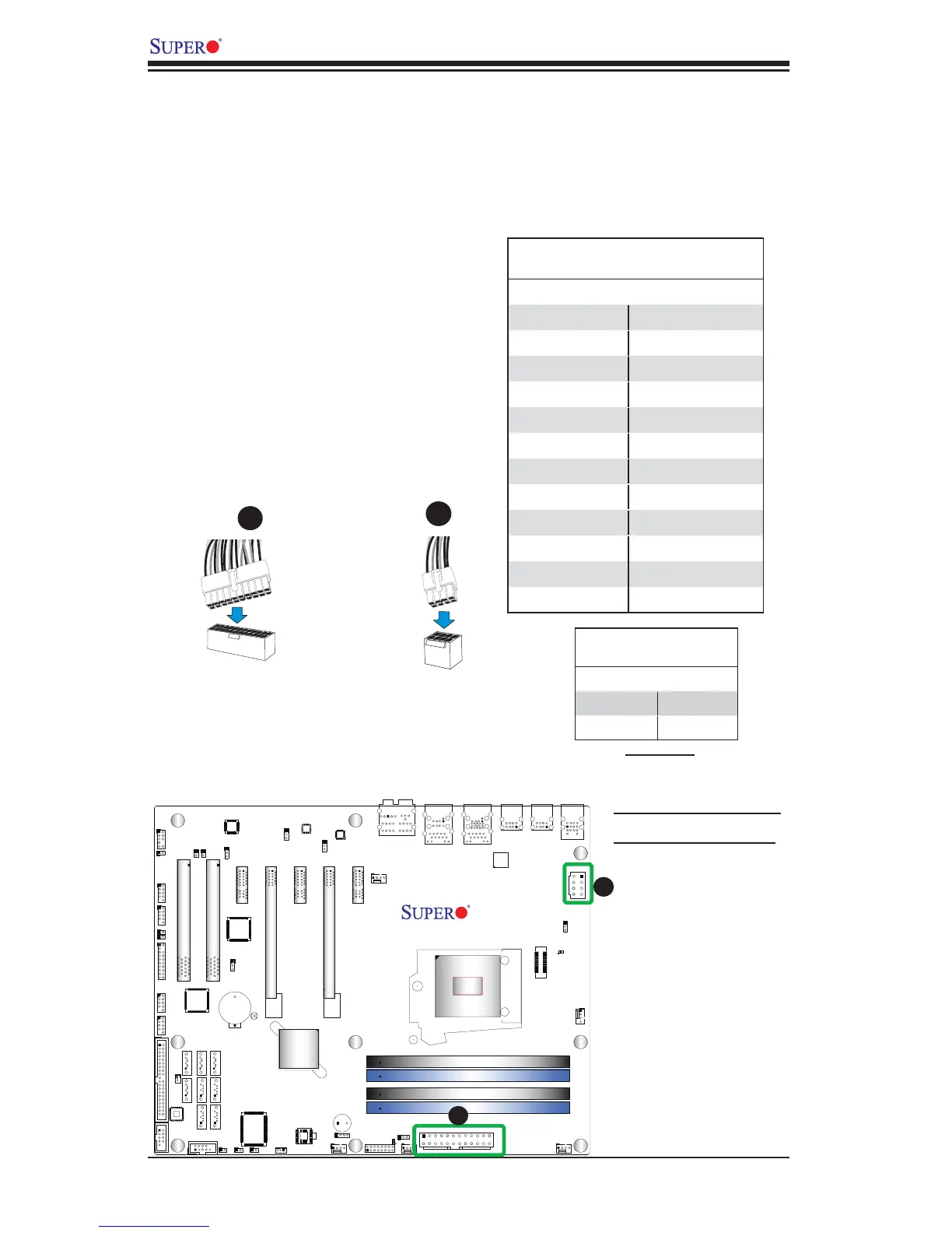
A. 24-Pin ATX Main PWR
B. 8-Pin Processor PWR
ATX Power 24-pin Connector
Pin Defi nitions (JPW1)
Pin# Defi nition Pin # Defi nition
13 +3.3V 1 +3.3V
14 -12V 2 +3.3V
15 COM 3 COM
16 PS_ON 4 +5V
17 COM 5 COM
18 COM 6 +5V
19 COM 7 COM
20 Res (NC) 8 PWR_OK
21 +5V 9 5VSB
22 +5V 10 +12V
23 +5V 11 +12V
24 COM 12 +3.3V
(Required)
12V 8-pin Power Connec-
tor Pin Defi nitions
Pins Defi nition
1 through 4 Ground
5 through 8 +12V
ATX Main PWR & CPU PWR
Connectors
The 24-pin main power connector
(JPW1) is used to provide power to
the motherboard. The 8-pin CPU PWR
connector (JPW2) is also required for
the processor. These power connectors
meet the SSI EPS 12V specifi cation. See
the table on the right for pin defi nitions.
8-Pin Processor PWR
A
B
24-Pin Main PWR
A
B