Chapter 2: Installation
2-15
Rev. 1.01
C7P67
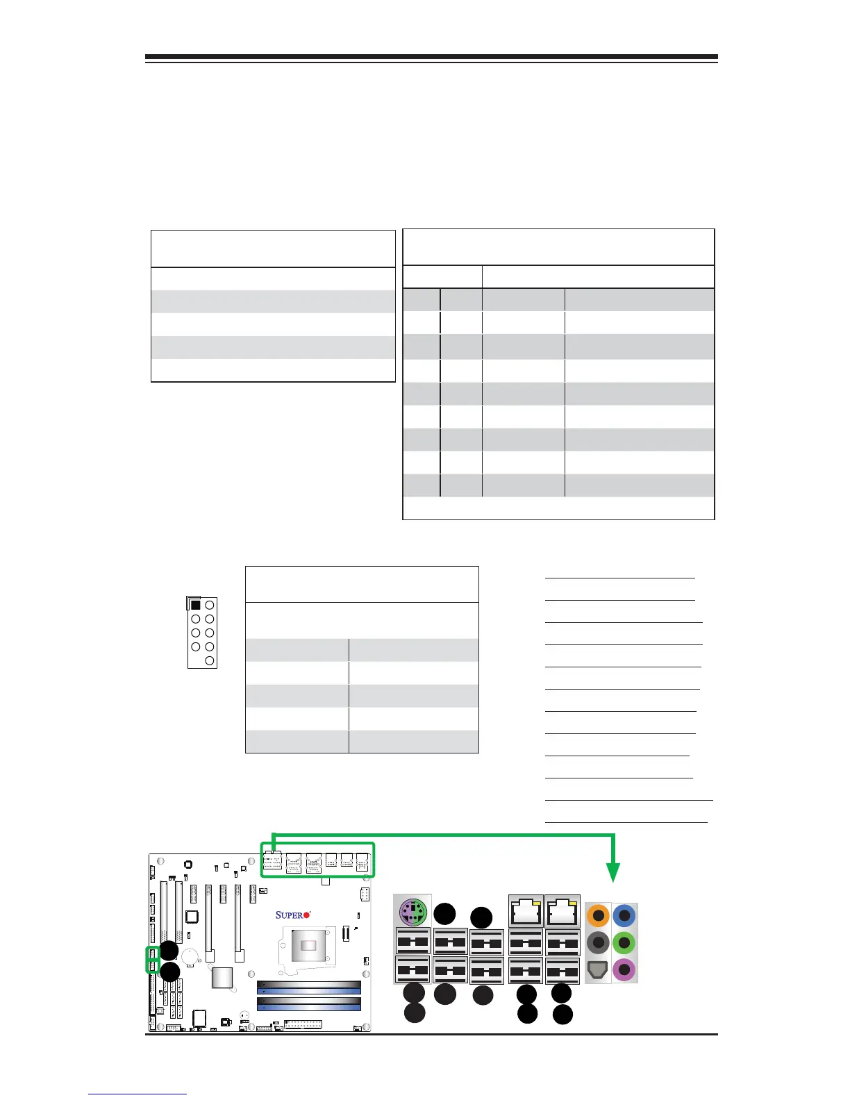
A. Backpanel USB 2.0 #8
B. Backpanel USB 2.0 #9
C. Backpanel USB 2.0 #13
D. Backpanel USB 2.0 #10
E. Backpanel USB 2.0 #11
F. Backpanel USB 2.0 #12
G. Backpanel USB 3.0 #0
H. Backpanel USB 3.0 #1
I. Backpanel USB 2.0 #0
J. Backpanel USB 2.0 #1
K. Front Panel USB 2.0 #2/3
l. Front Panel USB 2.0 #4/5
Universal Serial Bus (USB)
Eight Universal Serial Bus 2.0 ports (USB 8/9, 13/10, 11/12, and 0/1) are located
on the I/O back panel. In addition, two USB 3.0 Ports (USB 3.0 Ports 0/1) are also
located above GLAN Port 1 on the backplane. Additionally, USB 2/3, 4/5 are used
to provide front chassis access. USB Cables are not included. See the tables on
the right for pin defi nitions.
Back Panel USB (2.0) #0/1, 8/9, 11/12, 13/10
Pin Defi nitions
Pin# Defi nition Pin# Defi nition
1 +5V 5 +5V
2 USB_PN1 6 USB_PN0
3 USB_PP1 7 USB_PP0
4 Ground 8 Ground
Front Panel USB (2.0) #2/3, 4/5
Pin Defi nitions
USB 2/4
Pin # Defi nition
USB 3/5
Pin # Defi nition
1 +5V 2 +5V
3 USB_PN2 4 USB_PN3
5 USB_PP2 6 USB_PP3
7 Ground 8 Ground
9 Key 10 Ground
E
A
B
C
D
G
H
I
J
K
L
Back Panel USB (3.0) #0/1
Pin Defi nitions
Pin# Pin# Signal Name Description
1 10 VBUS Power
2 11 D- USB 2.0 Differential Pair
312D+
4 13 Ground Ground of PWR Return
5 14 StdA_SSRX- SuperSpeed Receiver
6 15 StdA_SSRX+ Differential Pair
7 16 GND_DRAIN Ground for Signal Return
8 17 StdA_SSTX- SuperSpeed Transmitter
9 18 StdA_SSTX+ Differential Pair
1
USB2/3
2
10