Chapter 2: Installation
2-23
JTPM1
M-SATA1
M-SATA0
I-SATA1
I-SATA0
LED1
JWOL
JF1
JPW1
JBT1
I-SATA5 I-SATA2
I-SATA4
I-SATA3
B1
SP1
JD1
JWF1
J15
1
JPME1
JHD_AC1
JSPDIF_IN
JSPDIF_OUT
JI2C1
JI2C2
JWOR
JL1
CATERR_LED1
JPW2
FANA
FAN4
FAN2
FAN1
FAN3
JPL1
JPAC1
JPI1
JPL2
JLED
1
JCPUVRD_SMB
SATA 3.0
USB3.0 0/1
IDE
1394_1
1394_2
Slot1 PCI 33MHZ
Slot2 PCI 33MHZ
Slot3 PCI-E 2.0 X1
Slot4 PCI-E 2.0 X8 (INX16)
Slot5 PCI-E 2.0 X1
Slot6 PCI-E 2.0 X16
Slot7 PCI-E 2.0 X1
USB11/12
USB13/10
USB8/9
AUDIO FP
USB2/3
USB4/5
Buzzer
COM2
COM1
HD AUDIO
LAN2
USB 2.0 0/1
Always Populate Blue Sockets First
Unbuf. Non-ECC DDR3 DIMM Required
LAN1
CPU
JITP1
DIMM2A
DIMM2B
DIMM1B
DIMM1A
KB/Mouse
Rev. 1.01
C7P67
J18
LAN CTRL
LAN CTRL
Audio CTRL
Battery
BIOS
USB 3.0 CTRL
Intel
P67 PCH
LGA1155
Marvel
SATA 3 CTRL
S I/O
1394
CTRL
PCI
CTRL
FP CTRL
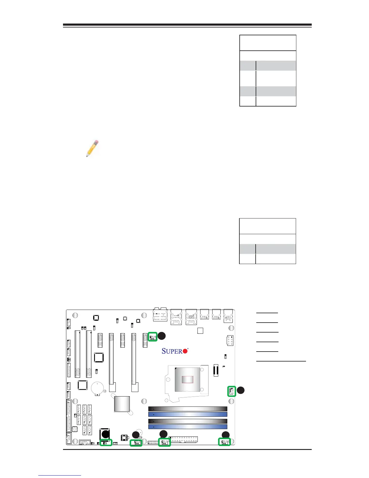
Fan Header
Pin Defi nitions
Pin# Defi nition
1 Ground (Black)
2 2.5A/+12V
(Red)
3 Tachometer
4 PWM_Control
Fan Headers
The C7P67 has fi ve fan headers (Fan 1~Fan
4 and Fan A). These fans are 4-pin fan head-
ers. However, Pins 1-3 of the fan headers are
backward compatible with the traditional 3-pin
fans. A fan speed control setting in the BIOS
Hardware Monitoring section allows the BIOS
to automatically set fan speeds based on the
system temperature. Refer to the table on the
right for pin defi nitions.
Note: Please use all 3-pin fans or all
4-pin fans on a motherboard. Please
do not use 3-pin fans and 4-pin fans
on the same board.
A
B
A. Fan 1
B. Fan 2
C. Fan 3
D. Fan 4
E. Fan A
F. Chassis Intrusion
C
D
E
Chassis Intrusion
A Chassis Intrusion header is located at JL1 on
the motherboard. Attach the appropriate cable
from the chassis to inform you of a chassis intru-
sion when the chassis is opened.
Chassis Intrusion
Pin Defi nitions (JL1)
Pin# Defi nition
1 Intrusion Input
2 Ground