Encoder wiring4)
Following items should be noticed in encoder wiring:a)
PG wire should be laid separately and keep distance from control circuit and driver circuit
and forbidden to parallel with them.
PG wire should be shield wire, and shield layer should connect to PE near controller. (In
order to avoid being disturbed, only one terminal connects to ground.)
PG wire should be pulled on pipe sep
arately, and metal crust should be connected to
ground credibility.
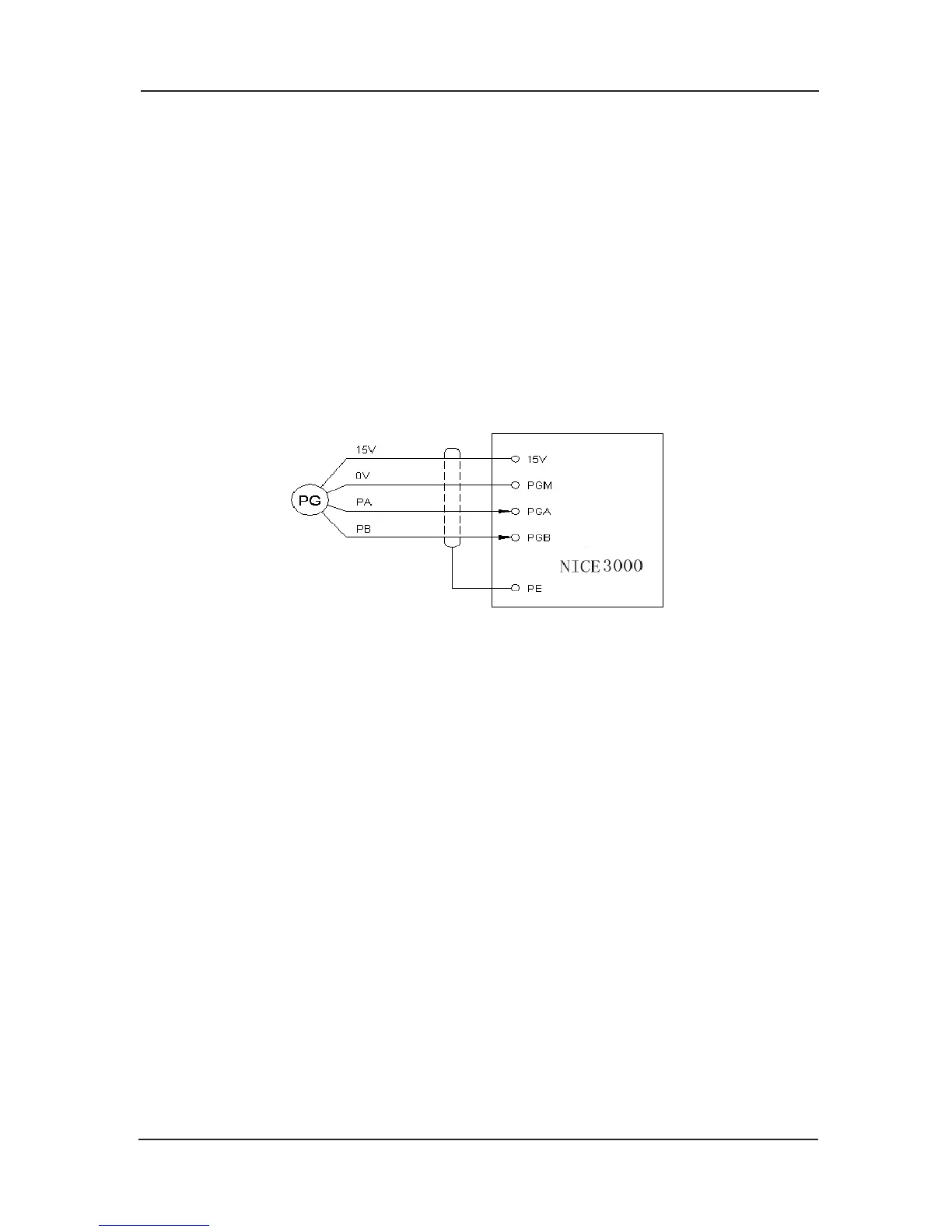
Encoder connection as follows:b)
Encoder connection of increment push-pull output and open collector output.
MCTC-MCB-A/B self-equipped with push-pull encoder trans-connection circuit. Its connection
is as follows:
Chart 4-7 connection of increment push-pull output and plough collector output encoder
Type U, V, W encoder wiringc)
For type UVW encoder, the controller of the main control board with the type MCTC-MCB-A
needs to equip with PG connection card MCTC-PG-B; the controller of the main control board
with the type MCTC-MCB-B needs to equip with PG connection card MCTC-PG-B and needs
to equip with MCTC-PG
-D through the slot J12 on the main control board.
Terminal instruction of MCTC-PG-B card
There are 15 user connection terminals and 16 pin interfaces with two lines, referring to
chart3-8. VCC and GND supply the encoder with work power; A+、A-、B+、B-、U+、
U-、V+、V-、W+、W- are encoder’s signal inputting terminal; COM, OUT-A, OUT-B are
frequency division signal outputting terminals; 16 pin interfaces con
nect to the bottom drive
board of the controller.
 Loading...