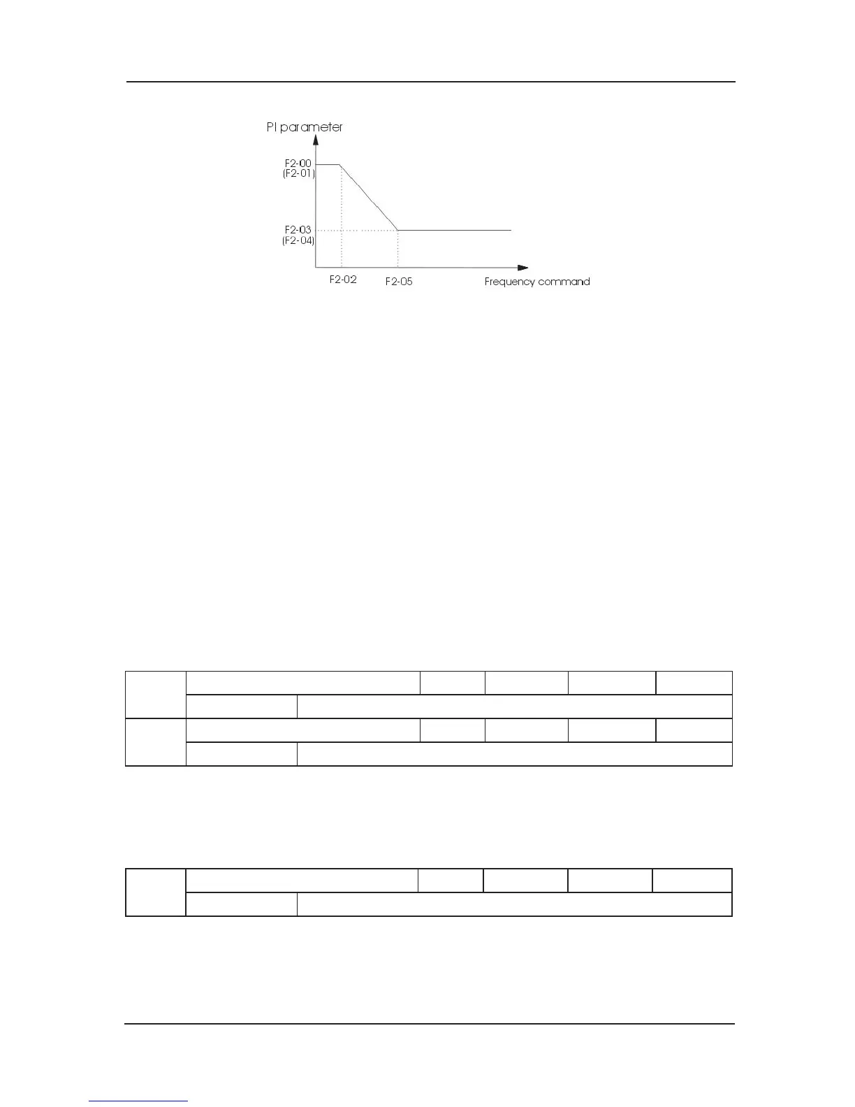
Fig 6-3 PI Parameters Schematic Diagram
It can regulate the speed dynamic response characteristic of the vector control by setting
the proportional coefficient and integrating time of the speed regulator. It can accelerate the
dynamic response of the speed loop by increasing the proportional gain or decreasing the
integrating time. Too large the proportional gain or too small the integrating time wi
ll cause the
system to vibrate.
The regulating methods are recommended as follows:
If the factory parameters cannot satisfy the requirements, conduct minor adjustment on the
basis of the factory parameters:
Enlarge the proportional gain first to prevent the system from vibrating, and then diminish the
integrating time to ensure that the system has fast response characteristic and small overshoot.
If s
witching frequency 1 and switching frequency 2 are set as 0 at the same time, only F2-03
and F2-04 are virtual value.
Note: Once the Pl parameters are set inappropriately, it will cause large overshoot speed and
even voltage fault when the overshoot returns to the normal level.
F2-06
Proportional gain of current loop Default 60 Min. Unit 1
Setting Range 100~500
F2-07
Integral gain of current loop Default 30 Min. Unit 1
Setting Range 100~500
F2-06, F2-07 are current loop adjusting parameters in the vector control arithmetic. The
adjusting method is the similar with that of parameter of speed loop P1. The adjustment in the
synchronous motor has a obvious effect on the feeling of comfort.
Appropriate adjustment can
restrain the vibration while the lift is running.
F2-08
Upper limit of torque Default 150.0% Min. Unit 0.1%
Setting Range 0.0~200.0%
It can set upper limit of torque of motor. The setup 100% corresponds to the rated torque of the
motor that matches the system.
 Loading...