It can set the pulse number of each rotation of the encoder, according to the nameplate of
encode.
Note: it must set the encoder pulse number correctly when it’s in the closed loop vector
control. Otherwise it cannot work normally. If the asynchronous motor still cannot work normally
after the encoder pulse number set correctly, please exchange the connection line between the
phase A and B of the e
ncoder. The encoder pulse number of permanent-magnet synchronous
motor must be set according to the UVW encoder, and the pulse number per rotation should be
set according to the encoder nameplate.
F1-13
Encode failure monitoring times Default 3.0s Min. Unit 0.1s
Setting Range 0.0~10.0s
It can set monitoring time when encode fault occurs. After lift starts running with speed of
nonzero, the system begins to receive signal of encoder every time of F1-13 setting. If there’s
none signal input, the system will show Err20 which means encoder failure.
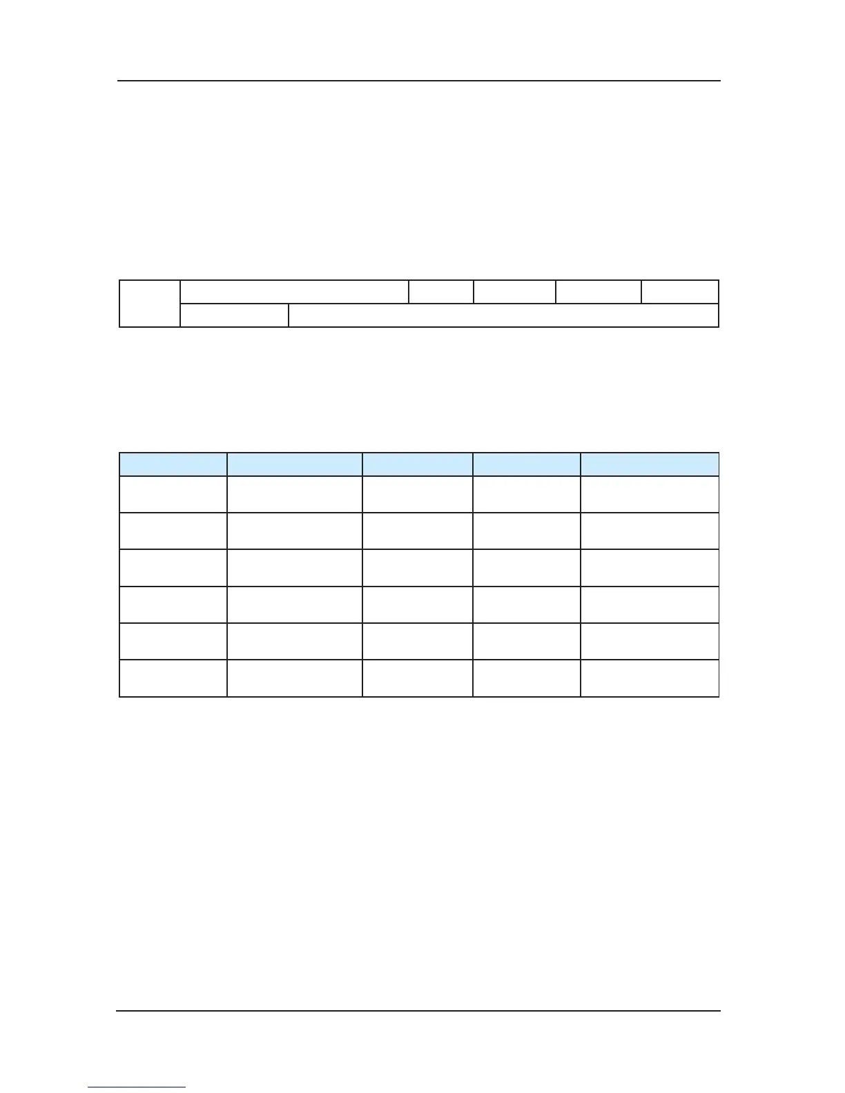
6.3 F2 Group Vector Control Parameters
Function code Name Default Min. Unit Setting Range
F2-00
Proportional gain 1
of speed loop
40 1 0~100
F2-01
Integration time 1
of speed loop
0.60s 0.01s 0.01~10.00s
F2-02
Switching
frequency 1
2.00Hz 0.01Hz 0.00~F2-05
F2-03
Proportional gain 2
of speed loop
35 1 0~100
F2-04
Integration time 2
of speed loop
0.80s 0.01s 0.01~10.00s
F2-05
Switching
frequency 2
5.00Hz 0.01Hz F2-02~F0-05
The parameters of F2-00 and F2-01 decide the dynamic response characteristic of the
frequency that is smaller than the switching frequency 1 (F2-02), while the parameters of F2-03
and F2-04 decide the dynamic response characteristic of the frequency that is larger than
the switching frequency 2 (F2-05). The dynamic response characteristic parameters of the
frequency between the switching frequency 1 and switching frequency 2 equal to the weighte
d
average value of two set of F2-00、F2-01 and F2-03、F2-04. As shown in Chart 6-2:
 Loading...