The no-display hall call board designed with 4 relay output, namely the K1、K2、K3 and K4,
output by CN2 terminal. Please refer to the fig 3-9-3 for details
HPB、LCD function 2)
Realization of HPB and LCD function a)
The dial switch bit definitions see Table 1
Terminal I/O definition b)
The input and communication interface definitions are same as the one of HCB-B, fig
3-9-3 for the CN2 terminal ,
see Table 2 for detailed functions and output interface.
See the Tanle 3 for the open collector output binary oor display.
segment code function 3)
The 7 segment function is applied to the freight elevator reformation, currently concern 1 Nixie
tube, and with specialized program it can be expanded.
Dial switch settings. a)
See Table 1 for the dial switch bit definitions
See Table 2 for the Input an
d communication interface
Output definition
Open collector output
Voice station report function 4)
Dial switch settings a)
See Table 1 for dial switch bit definition
See Table 2 for the input and communication interface.
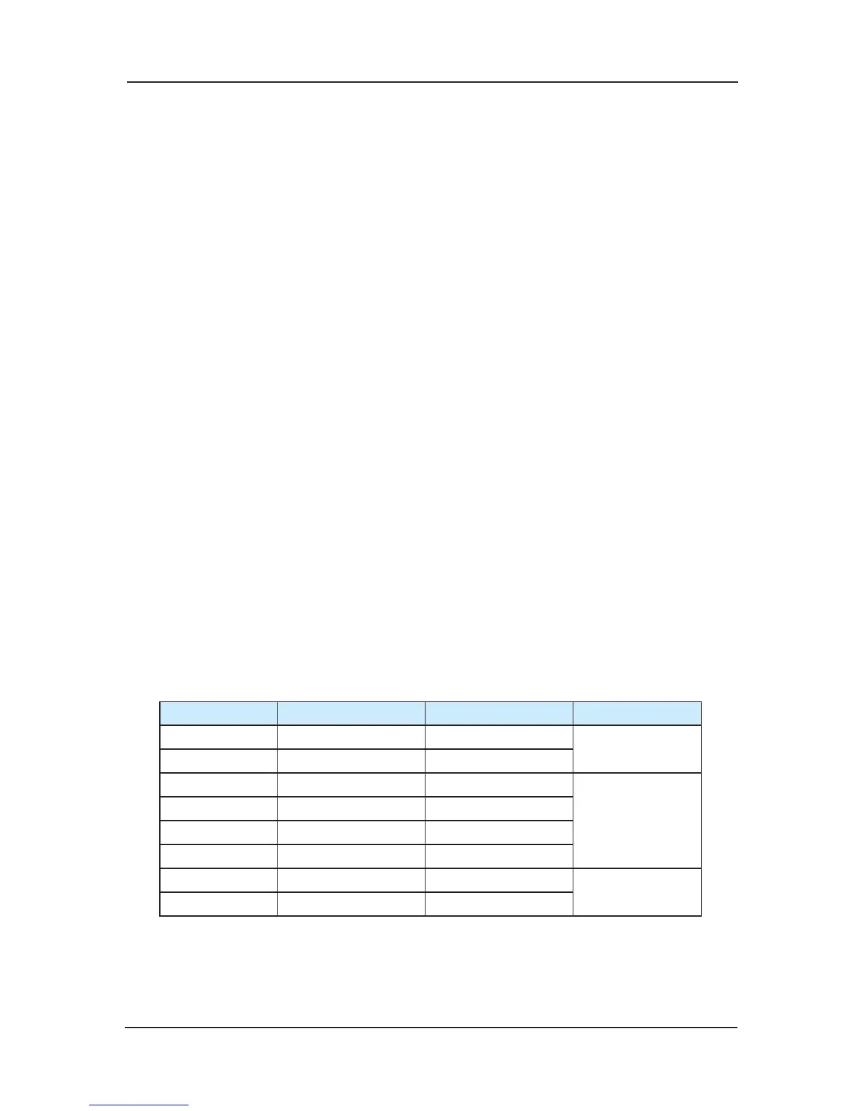
Settings of F2,F2,F0
Based on the settings of F0-F2, the voice reporter will give report for different oors.
F2 F1 F0
0 0 0 0,1-10
1 0 0
0 0 1 -1,0,1-10
0 1 0
1 0 1
1 1 0
0 1 1 -2,-1,0,1-10
1 1 1
Input and communication interface.b)
Communication interface as Table 1
The voice reporter has no input signal, so just neglect the JP1-JP6.
 Loading...