4A-7 Brake Control System and Diagnosis:
6) Close the air bleeder valve (1) and disconnect the
clear hose.
Tightening torque
Front brake air bleeder valve (a): 6 N·m (0.6 kgf-
m, 4.5 lb-ft)
7) Fill the reservoir with brake fluid.
8) Reinstall the diaphragm and reservoir cap.
Front Brake Hose Removal and Installation
B827H14106011
Removal
CAUTION
!
Make sure that the vehicle is holded securely.
1) Drain brake fluid. Refer to “Brake Fluid Replacement
(Page 4A-6)”.
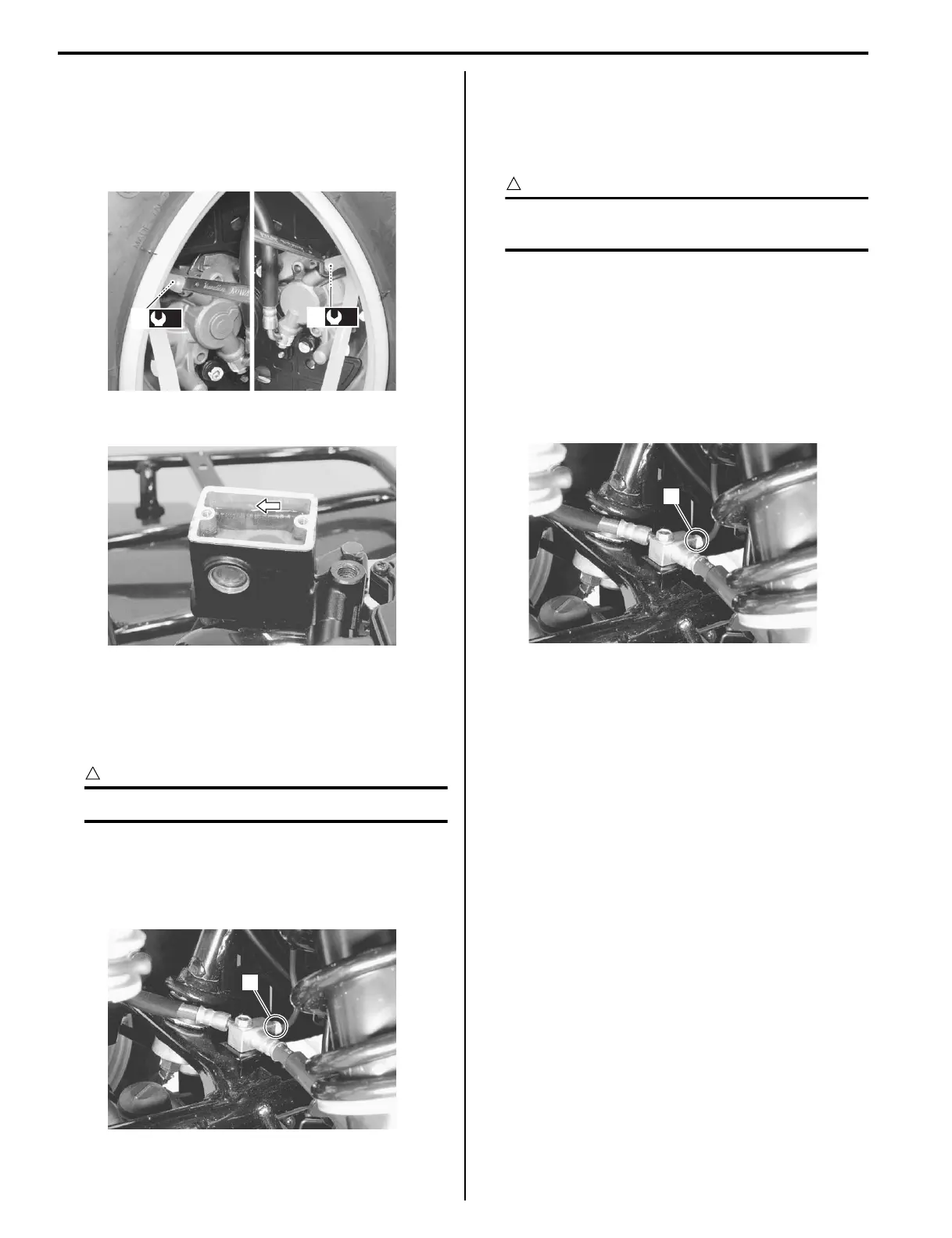
2) Loosen the flare nuts (1) and disconnect the brake
pipe.
3) Remove the front brake hoses as shown in the front
brake hose routing diagram. Refer to “Front Brake
Hose Routing Diagram (Page 4A-1)”.
Installation
CAUTION
!
The seal washers should be replaced with the
new ones to prevent fluid leakage.
1) Install the front brake hoses as shown in the front
brake hose routing diagram. Refer to “Front Brake
Hose Routing Diagram (Page 4A-1)”.
2) Tighten the brake flare nut (1) to the specified
torque.
Tightening torque
Brake pipe flare nut (a): 16 N·m (1.6 kgf-m, 11.5
lb-ft)
3) Bleed air from the front brake system. Refer to “Air
Bleeding from Front Brake Fluid Circuit (Page 4A-
5)”.
Rear Brake Cable Removal and Installation
B827H14106012
Removal
1) Remove the right footrest mudguard. Refer to
“Exterior Parts Removal and Installation in Section
9D (Page 9D-3)”.
2) Remove the rear blake cable as shown in the blake
cable routing diagram. Refer to “Brake Cable
Routing Diagram (Page 4A-2)”.
Installation
1) Install the rear brake cable as shown in the brake
cable routing diagram. Refer to “Brake Cable
Routing Diagram (Page 4A-2)”.
2) After installing the rear brake cable, check the brake
pedal free travel. Refer to “Rear Brake Pedal / Rear
Brake (Parking Brake) Lever Inspection and
Adjustment in Section 0B (Page 0B-16)”.
3) Reinstall the footrest mudguard.
(a)
1
(a)
1
I827H1410015-01
I827H1410016-01
1
I827H1410017-01
1
I827H1410018-01